Stress distribution in premolars restored with inlays or onlays: 3D finite element analysis
- Affiliations
-
- 1Department of Prosthodontics, School of Dentistry, Chonnam National University, Gwangju, Republic of Korea.
- 2Department of Periodontology, School of Dentistry, Chonnam National University, Gwangju, Republic of Korea. hjchung@jnu.ac.kr
- KMID: 2413486
- DOI: http://doi.org/10.4047/jap.2018.10.3.184
Abstract
- PURPOSE
To analyze stress distribution in premolars restored with inlays or onlays using various materials.
MATERIALS AND METHODS
Three-dimensional maxillary premolar models of abutments were designed to include the following: 1) inlay with O cavity (O group), 2) inlay with MO cavity (MO group), 3) inlay with MOD cavity (MOD group), and 4) onlay (ONLAY group). A restoration of each inlay or onlay cavity was simulated using gold alloy, e.max ceramic, or composite resin for restoration. To simulate masticatory forces, a total of 140 N static axial force was applied onto the tooth at the occlusal contact areas. A finite element analysis was performed to predict the magnitude and pattern of stresses generated by occlusal loading.
RESULTS
Maximum von Mises stress values generated in the abutment teeth of the ONLAY group were ranged from 26.1 to 26.8 MPa, which were significantly lower than those of inlay groups (O group: 260.3-260.7 MPa; MO group: 252.1-262.4 MPa; MOD group: 281.4-298.8 MPa). Maximum von Mises stresses generated with ceramic, gold, and composite restorations were 280.1, 269.9, and 286.6 MPa, respectively, in the MOD group. They were 252.2, 248.0, 255.1 MPa, respectively, in the ONLAY group.
CONCLUSION
The onlay design (ONLAY group) protected tooth structures more effectively than inlay designs (O, MO, and MOD groups). However, stress magnitudes in restorations with various dental materials exhibited no significant difference among groups (O, MO, MOD, ONLAY).
Keyword
MeSH Terms
Figure
-
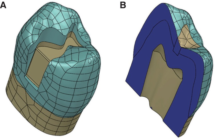
Fig. 1 (A) MO cavity was created on the 3-D CAD model of the maxillary premolar tooth. (B) Cross-sectional view of premolar tooth showing the enamel, dentin and pulp chamber.
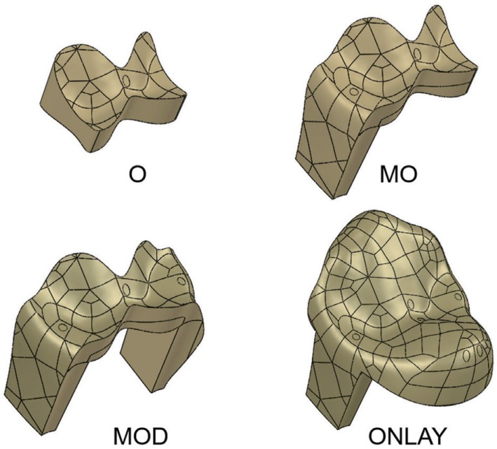
Fig. 2 Models of 3 inlays and 1 onlay bodies restored on the maxillary second premolars. (O), Class I inlay with butt joint and 0.9 mm-wide isthmus. (MO), Class II MO inlay with a mesial proximal box. (MOD), Class II inlay with both mesial and distal proximal boxes. (ONLAY), Onlay completely covers the occlusal surface with proximal boxes.
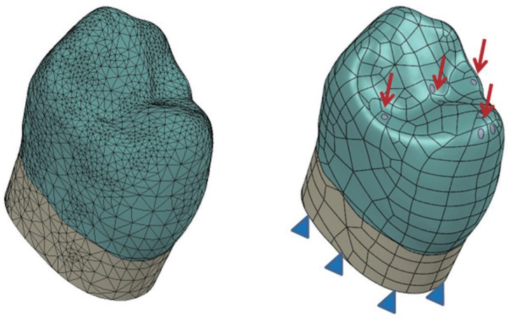
Fig. 3 3-D solid models meshed with tetrahedral elements. All nodes on the lower surface of the tooth were constrained in all directions (X, Y, and Z), as a boundary condition. The static axial force was applied vertically onto the tooth at occlusal contact points (palatal cusp, central fossa, and marginal ridges).
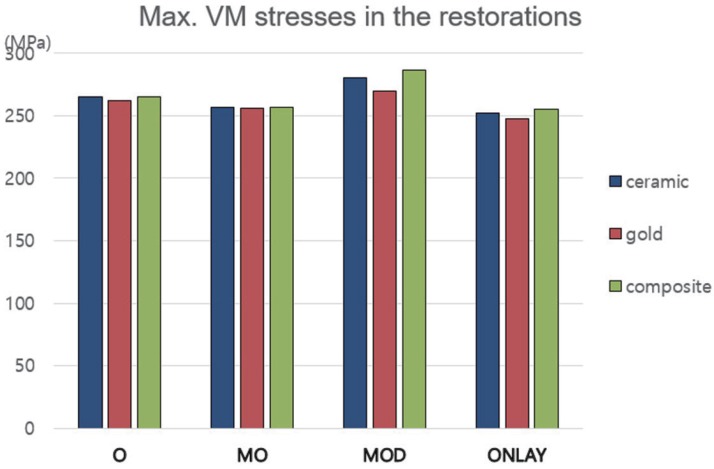
Fig. 4 Maximum von Mises stresses generated in restorations with various dental materials. Stress magnitudes in restorations restored with various dental materials showed relatively little differences among groups of O, MO, MOD and ONLAY.
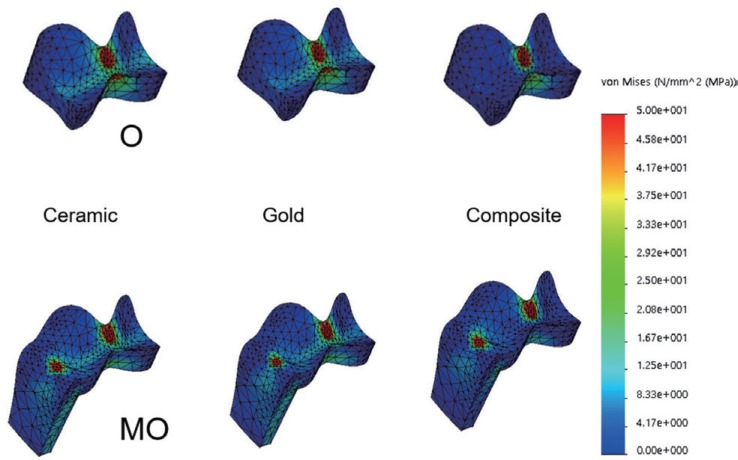
Fig. 5 Similar distribution and concentration pattern of von Mises stresses in restoration of the O group and the MO group during mastication. High stress concentration areas were generated at the loading site near central fossa in the O group. Marginal ridge and central fossa area generated maximum values in the MO group.
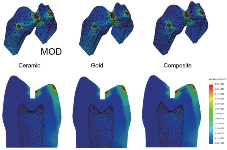
Fig. 6 Stress concentration localized around the central fossa and marginal ridges of MOD group regardless of various restorative materials.
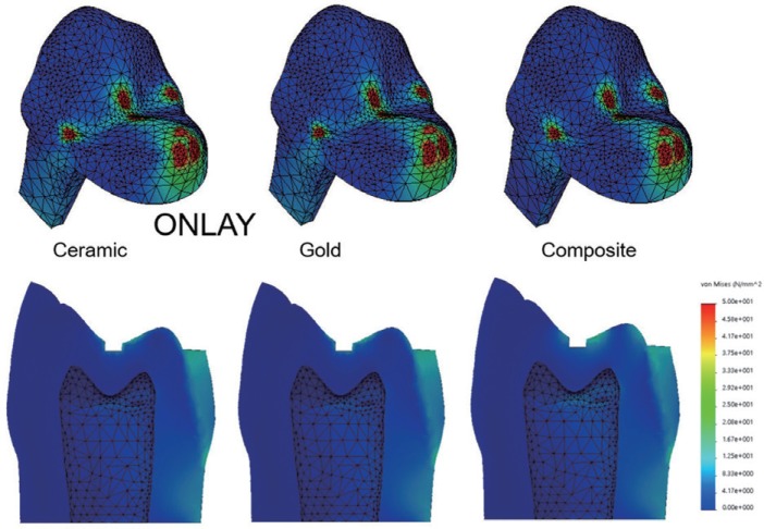
Fig. 7 High von Mises stress concentration areas were observed at the loading site near the lingual cusp tip, marginal ridges and central fossa in onlay body regardless of various restorative materials. The ONLAY group showed a favorable distribution of stresses in the abutment tooth. Only a small value of von Mises stresses and slight difference in stress gradient were found in tooth structures.

Fig. 8 Maximum von Mises stresses generated in the abutment teeth with various dental materials. Stress values in ONLAY group were significantly lower than those of inlay groups (O, MO, MOD).
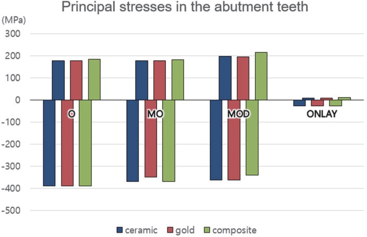
Fig. 9 Maximum and minimum principal stresses generated in the abutment teeth with various dental materials. Bars with minus direction denote the minimum principal (compressive) stresses. Bars with plus direction show the maximum principal (tensile) stress. Magnitude tendencies of principal stress are similar to the values of von Mises stress shown in Fig. 8. Stress values in ONLAY group are significantly lower than those of inlay groups (O, MO, and MOD).
Reference
-
1. Shillingburg HT, Sather DA, Wilson EL, Cain JR, Mitchell DL, Blanco LJ, Kessler JC. Fundamentals of fixed prosthodontics. 4th ed. Chicago: Quintessence;2012. p. 193–227.2. Reeh ES, Messer HH, Douglas WH. Reduction in tooth stiffness as a result of endodontic and restorative procedures. J Endod. 1989; 15:512–516. PMID: 2639947.
Article3. Stappert CF, Guess PC, Gerds T, Strub JR. All-ceramic partial coverage premolar restorations. Cavity preparation design, reliability and fracture resistance after fatigue. Am J Dent. 2005; 18:275–280. PMID: 16296437.4. Arnelund CF, Johansson A, Ericson M, Häger P, Fyrberg KA. Five-year evaluation of two resin-retained ceramic systems: a retrospective study in a general practice setting. Int J Prosthodont. 2004; 17:302–306. PMID: 15237876.5. Cubas GB, Habekost L, Camacho GB, Pereira-Cenci T. Fracture resistance of premolars restored with inlay and onlay ceramic restorations and luted with two different agents. J Prosthodont Res. 2011; 55:53–59. PMID: 20934401.
Article6. Kantardzić I, Vasiljević D, Blazić L, Luzanin O. Influence of cavity design preparation on stress values in maxillary premolar: a finite element analysis. Croat Med J. 2012; 53:568–576. PMID: 23275322.
Article7. Christensen GJ. The coming demise of the cast gold restoration? J Am Dent Assoc. 1996; 127:1233–1236. PMID: 8803400.
Article8. Costa A, Xavier T, Noritomi P, Saavedra G, Borges A. The influence of elastic modulus of inlay materials on stress distribution and fracture of premolars. Oper Dent. 2014; 39:E160–E170. PMID: 24967990.
Article9. Mondelli J, Steagall L, Ishikiriama A, de Lima Navarro MF, Soares FB. Fracture strength of human teeth with cavity preparations. J Prosthet Dent. 1980; 43:419–422. PMID: 6928479.
Article10. Dejak B, Mlotkowski A, Romanowicz M. Strength estimation of different designs of ceramic inlays and onlays in molars based on the Tsai-Wu failure criterion. J Prosthet Dent. 2007; 98:89–100. PMID: 17692590.
Article11. Yamanel K, Caglar A, Gülsahi K, Ozden UA. Effects of different ceramic and composite materials on stress distribution in inlay and onlay cavities: 3-D finite element analysis. Dent Mater J. 2009; 28:661–670. PMID: 20019416.
Article12. Jiang W, Bo H, Yongchun G, LongXing N. Stress distribution in molars restored with inlays or onlays with or without endodontic treatment: a three-dimensional finite element analysis. J Prosthet Dent. 2010; 103:6–12. PMID: 20105674.
Article13. Zarone F, Sorrentino R, Apicella D, Valentino B, Ferrari M, Aversa R, Apicella A. Evaluation of the biomechanical behavior of maxillary central incisors restored by means of endocrowns compared to a natural tooth: a 3D static linear finite elements analysis. Dent Mater. 2006; 22:1035–1044. PMID: 16406084.
Article14. Ereifej N, Rodrigues FP, Silikas N, Watts DC. Experimental and FE shear-bonding strength at core/veneer interfaces in bilayered ceramics. Dent Mater. 2011; 27:590–597. PMID: 21477853.
Article15. Moon SY, Lim YJ, Kim MJ, Kwon HB. Three-dimensional finite element analysis of platform switched implant. J Adv Prosthodont. 2017; 9:31–37. PMID: 28243389.16. Song HY, Huh YH, Park CJ, Cho LR. A two-short-implantsupported molar restoration in atrophic posterior maxilla: A finite element analysis. J Adv Prosthodont. 2016; 8:304–312. PMID: 27555900.
Article17. Ausiello P, Franciosa P, Martorelli M, Watts DC. Numerical fatigue 3D-FE modeling of indirect composite-restored posterior teeth. Dent Mater. 2011; 27:423–430. PMID: 21227484.
Article18. St-Georges AJ, Sturdevant JR, Swift EJ Jr, Thompson JY. Fracture resistance of prepared teeth restored with bonded inlay restorations. J Prosthet Dent. 2003; 89:551–557. PMID: 12815348.
Article19. Cohen S, Berman LH, Blanco L, Bakland L, Kim JS. A demographic analysis of vertical root fractures. J Endod. 2006; 32:1160–1163. PMID: 17174672.
Article20. Thompson MC, Thompson KM, Swain M. The all-ceramic, inlay supported fixed partial denture. Part 1. Ceramic inlay preparation design: a literature review. Aust Dent J. 2010; 55:120–127. PMID: 20604751.
Article21. Frankenberger R, Taschner M, Garcia-Godoy F, Petschelt A, Krämer N. Leucite-reinforced glass ceramic inlays and onlays after 12 years. J Adhes Dent. 2008; 10:393–398. PMID: 19058686.22. Tang CB, Liul SY, Zhou GX, Yu JH, Zhang GD, Bao YD, Wang QJ. Nonlinear finite element analysis of three implantabutment interface designs. Int J Oral Sci. 2012; 4:101–108. PMID: 22699263.
Article23. Molin MK, Karlsson SL. A randomized 5-year clinical evaluation of 3 ceramic inlay systems. Int J Prosthodont. 2000; 13:194–200. PMID: 11203631.
- Full Text Links
-
- Actions
-
Cited
- CITED
-
- Close
- Share
-
- Similar articles
-
- Stress distribution of endodontically treated maxillary second premolars restored with different methods: Three-dimensional finite element analysis
- The effect of restorative materials on the stress distribution of class V composite resin restorations: a 3D finite element investigation
- The influence of combining composite resins with different elastic modulus on the stress distribution of Class V restoration: a three-dimensional finite element study
- Effects of occlusal load on the stress distribution of four cavity configurations of noncarious cervical lesions: a three-dimensional finite element analysis study
- Effect of the marginal position of prosthesis on stress distribution of teeth with abfraction lesion using finite element analysis
