Effects of orthodontic mini-implant position in the dragon helix appliance on tooth displacement and stress distribution: a three-dimensional finite element analysis
- Affiliations
-
- 1Division of Orthodontics, Department of Dentistry, University of Nebraska Medical Center, USA.
- 2Department of Orthodontics, Graduate School of Clinical Dentistry, Ewha Womans University, Korea.
- 3Division of Orthodontics, Department of Dentistry, College of Medicine, The Catholic University of Korea, St. Mary's Hospital, Korea.
- 4Department of Orthodontics, University of Ulsan College of Medicine, Asan Medical Center, Korea.
- 5School of Mechanical and Automobile Engineering, Kunsan National University, Korea.
- 6Division of Orthodontics, Department of Dentistry, School of Medicine, Ewha Womans University, Korea. yschun@ewha.ac.kr
- KMID: 1975431
- DOI: http://doi.org/10.4041/kjod.2011.41.3.191
Abstract
OBJECTIVE
The purpose of this study was to investigate the stress distribution on the orthodontic mini-implant (OMI) surface and periodontal ligament of the maxillary first and second molars as well as the tooth displacement according to the OMI position in the dragon helix appliance during scissors-bite correction.
METHODS
OMIs were placed at two maxillary positions, between the first and the second premolars (group 1) and between the second premolar and the first molar (group 2). The stress distribution area (SDA) was analyzed by three-dimensional finite element analysis.
RESULTS
The maximal SDA of the OMI did not differ between the groups. It was located at the cervical area and palatal root apex of the maxillary first molar in groups 1 and 2, respectively, indicating less tipping in group 2. The minimal SDA was located at the root and furcation area of the maxillary second molar in groups 1 and 2, respectively, indicating greater palatal crown displacement in group 2.
CONCLUSIONS
Placement of the OMI between the maxillary second premolar and the maxillary first molar to serve as an indirect anchor in the dragon helix appliance minimizes anchorage loss while maximizing the effect on scissors-bite correction.
Keyword
MeSH Terms
Figure
-
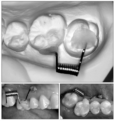
Fig. 1 Clinical application of the dragon helix appliance for tipping and intruding the maxillary second molar.

Fig. 2 The stress distribution on the periodontal ligament of the maxillary first and second molars as well as the orthodontic mini-implant (OMI) according to the OMI position. The color change from blue to red indicates increase in force. 4th & 5th OMI and 5th & 6th OMI indicate OMIs implanted between 1st and 2nd premolars, and between 2nd premolar and 1st molars, respectively.
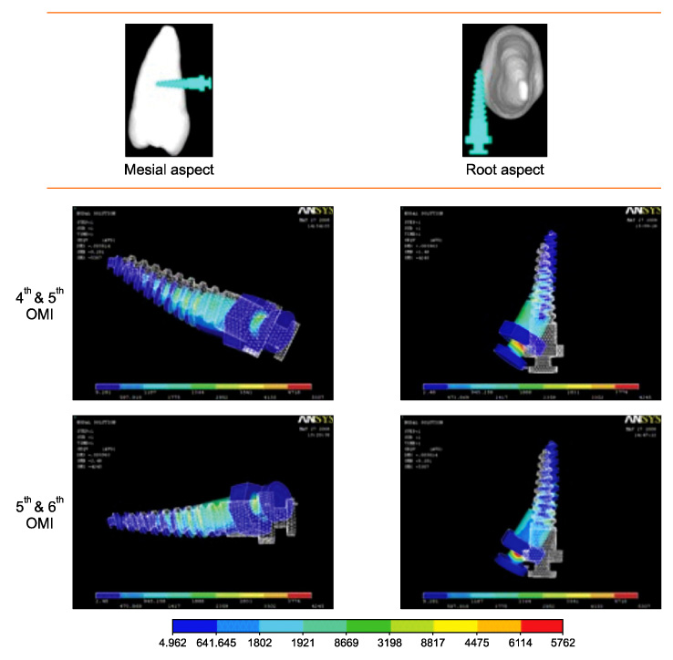
Fig. 3 Displacement of the orthodontic mini-implant according to its position (magnification, × 500). White and blue indicate before and after the force application, respectively. 4th & 5th OMI and 5th & 6th OMI indicate OMIs implanted between 1st and 2nd premolars, and between 2nd premolar and 1st molars, respectively.

Fig. 4 Graph representing the displacement of the OMI (from the center of the head to the screw end tip, magnification × 1,000). The larger X, Y, and Z values indicate mesial, buccal, and apical movements, respectively. OMI, Orthodontic mini-implant; 4 - 5, between 1st and 2nd premolars; 5 - 6, between 2nd premolar and 1st molar.
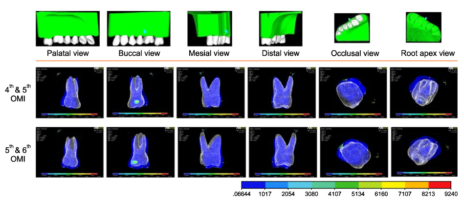
Fig. 5 Displacement of the maxillary first molar according to mini-implant's position. White and blue indicate before and after the force application, respectively. 4th & 5th OMI and 5th & 6th OMI indicate OMIs implanted between 1st and 2nd premolars, and between 2nd premolar and 1st molars, respectively.
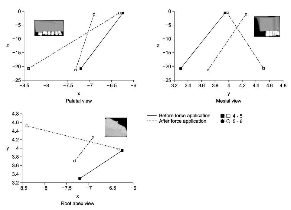
Fig. 6 Graph representing the displacement of the maxillary first molar (from the palatal cusp tip to the palatal root apex, magnification × 50). The larger X, Y, and Z values indicate mesial, buccal, and apical movements, respectively. 4 - 5, between 1st and 2nd premolars; 5 - 6, between 2nd premolar and 1st molar.

Fig. 7 Displacement of the maxillary second molar according to mini-implant's position. White and blue indicate before and after force application, respectively. 4th & 5th OMI and 5th & 6th OMI indicate OMIs implanted between 1st and 2nd premolars, and between 2nd premolar and 1st molars, respectively.
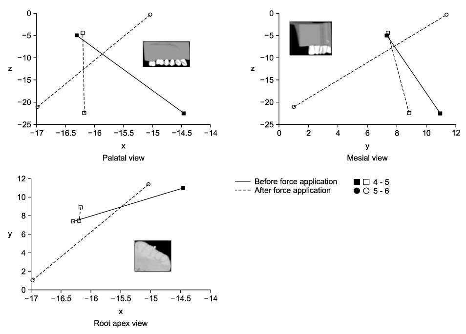
Fig. 8 Graph representing displacement of the maxillary second molar (from the palatal cusp tip to the palatal root apex, magnification × 50). The larger X, Y, and Z values indicate mesial, buccal, and apical movements, respectively. 4 - 5, between 1st and 2nd premolars; 5 - 6, between 2nd premolar and 1st molar.
Cited by 2 articles
-
Correction of dental Class III with posterior open bite by simple biomechanics using an anterior C-tube miniplate
Hyo-Won Ahn, Kyu-Rhim Chung, Suk-Man Kang, Lu Lin, Gerald Nelson, Seong-Hun Kim
Korean J Orthod. 2012;42(5):270-278. doi: 10.4041/kjod.2012.42.5.270.Torque control during lingual anterior retraction without posterior appliances
Sung-Seo Mo, Seong-Hun Kim, Sang-Jin Sung, Kyu-Rhim Chung, Yun-Sic Chun, Yoon-Ah Kook, Gerald Nelson
Korean J Orthod. 2013;43(1):3-14. doi: 10.4041/kjod.2013.43.1.3.
Reference
-
1. Yun SW, Lim WH, Chong DR, Chun YS. Scissors-bite correction on second molar with a dragon helix appliance. Am J Orthod Dentofacial Orthop. 2007. 132:842–847.
Article2. Harper DL. A case report of a Brodie bite. Am J Orthod Dentofacial Orthop. 1995. 108:201–206.
Article3. Orton-Gibbs S, Orton S, Orton H. Eruption of third permanent molars after the extraction of second permanent molars. Part 2: Functional occlusion and periodontal status. Am J Orthod Dentofacial Orthop. 2001. 119:239–244.
Article4. Ramsay DS, Wallen TR, Bloomquist DS. Case report MM. Surgical-orthodontic correction of bilateral buccal crossbite (Brodie syndrome). Angle Orthod. 1990. 60:305–311.5. Kucher G, Weiland FJ. Goal-oriented positioning of upper second molars using the palatal intrusion technique. Am J Orthod Dentofacial Orthop. 1996. 110:466–468.
Article6. Chun YS, Woo YJ, Row J, Jung EJ. Maxillary molar intrusion with the molar intrusion arch. J Clin Orthod. 2000. 34:90–93.7. Legan HL. Orthodontic planning and biomechanics for transverse distraction osteogenesis. Semin Orthod. 2001. 7:160–168.
Article8. Park YC, Lee SY, Kim DH, Jee SH. Intrusion of posterior teeth using mini-screw implants. Am J Orthod Dentofacial Orthop. 2003. 123:690–694.
Article9. Kanomi R. Mini-implant for orthodontic anchorage. J Clin Orthod. 1997. 31:763–767.10. Cope JB. Temporary anchorage devices in orthodontics: a paradigm shift. Semin Orthod. 2005. 11:3–9.
Article11. Celenza F, Hochman MN. Absolute anchorage in orthodontics: direct and indirect implant-assisted modalities. J Clin Orthod. 2000. 34:397–402.12. Kyung SH, Choi HW, Kim KH, Park YC. Bonding orthodontic attachments to miniscrew heads. J Clin Orthod. 2005. 39:348–353.13. Kyung SH, Lim JK, Park YC. The use of miniscrew as an anchorage for the orthodontic tooth movement. Korean J Orthod. 2001. 31:415–424.14. Bae SM, Park HS, Kyung HM, Kwon OW, Sung JH. Clinical application of micro-implant anchorage. J Clin Orthod. 2002. 36:298–302.15. Park HS, Kwon OW, Sung JH. Uprighting second molars with micro-implant anchorage. J Clin Orthod. 2004. 38:100–103.16. Park HS. Orthodontic treatment using micro-implant. 2006. 2nd ed. Seoul: Daehan Narae Publishing Inc.;1–414.17. Wilmes B, Su YY, Drescher D. Insertion angle impact on primary stability of orthodontic mini-implants. Angle Orthod. 2008. 78:1065–1070.
Article18. Lee KJ, Joo E, Kim KD, Lee JS, Park YC, Yu HS. Computed tomographic analysis of tooth-bearing alveolar bone for orthodontic miniscrew placement. Am J Orthod Dentofacial Orthop. 2009. 135:486–494.
Article19. Lim JE, Lim WH, Chun YS. Cortical bone thickness and root proximity at mandibular interradicular sites: implications for orthodontic mini-implant placement. Korean J Orthod. 2008. 38:397–406.
Article20. Park HS. An anatomical study using CT images for the implantation of micro-implants. Korean J Orthod. 2002. 32:435–441.21. Kim CN, Sung JH, Kyung HM. Three-dimensional finite element analysis of initial tooth displacement according to force application point during maxillary six anterior teeth retraction using skeletal anchorage. Korean J Orthod. 2003. 33:339–350.22. Cheon OJ, Kim TW, Suhr CH. Three-dimentional finite element analysis of the phenomenon produced during retraction of four maxillary incisors. Korean J Orthod. 1995. 25:525–541.23. Yoon HJ, Lim YK, Lee DY, Jo YS. Three-dimensional finite element analysis on the effect of maxillary incisor torque. Korean J Orthod. 2005. 35:137–147.
- Full Text Links
-
- Actions
-
Cited
- CITED
-
- Close
- Share
-
- Similar articles
-
- Three-dimensional finite element analysis for stress distribution on the diameter of orthodontic mini-implants and insertion angle to the bone surface
- Contact non-linear finite element model analysis of initial stability of mini implant
- The pattern of movement and stress distribution during retraction of maxillary incisors using a 3-D finite element method
- Finite element stress analysis of maxillary two implants-retained overdenture according go position of implant fixtures
- Three-dimensional finite element analysis of the splinted implant prosthesis in a reconstructed mandible
