Ultrasound-Guided Intervention in Cervical Spine
- Affiliations
-
- 1Sun's Orthopaedic Clinic, Seoul, Korea.
- 2Department of Orthopedic Surgery, Seoul Sacred Heart General Hospital, Seoul, Korea. msh124@paran.com
- KMID: 2106743
- DOI: http://doi.org/10.4055/jkoa.2015.50.2.77
Abstract
- Interventional procedures around the cervical spine have been classically performed under the guidance of fluoroscopy with radiation hazards to patients and doctors. Even though under fluoroscopic guidance, vascular and nerve structures cannot be shown and there are actual risks for the patient. Nowadays, we can use high resolution image ultrasound around cervical spine procedures. Real time imaging is possible. Cervical root block, medial branch block and many other interventions can be performed under ultrasound guidance. In out-patient clinics, ultrasound is very helpful in management of cervical problems in differentiating the origin of pain and treatment for the pain. Ultrasound is radiation free, easy to use and the imaging can be performed continuously while the injectant is visualized in real-time, increasing the precision of injection. Importantly, ultrasound enables visualization of major nerves and vessels and thus leads to improved safety of cervical interventions by decreasing the incidence of injury or injection into nearby vasculature. We therefore performed a review to investigate the feasibility of performing cervical interventions under real-time ultrasound guidance.
Keyword
Figure
-
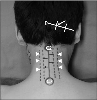
Figure 1 Surface anatomy of the posterior neck region. After dividing the line from external occipital protuberance to mastoid process into 3 sections, greater occipital nerve usually runs the point at the junction of its middle and medial thirds (white arrow). Drawing the line one finger breadth laterally from midline, there are laminae on this line (black arrows). Two finger breadths laterally, facet joints are on this line (arrowheads). E, external occipital protuberance; C2, spinous process of the 2nd cervical vertebra; C7, spinous process of the 7th cervical vertebra.

Figure 2 Surface anatomy of the anterior neck region. Below the chin, hyoid bone (H) situated opposite the 3rd cervical vertebra can be easily palpated at midline. A finger's breadth below, there is the laryngeal prominence of the thyroid cartilage (T). The outlines of the thyroid cartilage are readily palpated. Below its lower, anterior part of the cricoid cartilage (C) forms an important landmark on the front of the neck because it lies opposite the 6th cervical vertebra. Arrow indicates sternocleidomastoid muscle.
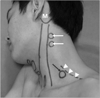
Figure 3 Surface anatomy of the lateral neck region. Below mastoid process (M), articular pillars (white arrows) can be palpated. At base of neck, transverse process of the 7th cervical vertebra (black arrow) can be palpated deeply at the anterior border of trapezius (arrowheads).
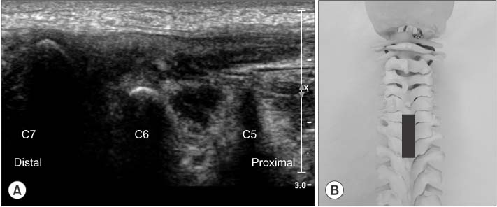
Figure 4 (A) Ultrasonography on longitudinal scan at midline of the posterior cervical area shows the prominent 7th spinous process from which other cervical spinous processes can be counted upwards. (B) Position of probe (black bar) for (A) on the artificial spine model.
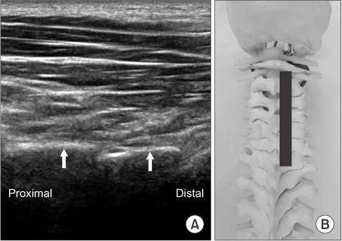
Figure 5 (A) Ultrasonography on posterior longitudinal paravertebral sonogram shows laminae of cervical spines (arrows). (B) Position of probe for (A) on the artificial spine model.

Figure 6 (A) Ultrasonography on longitudinal scan at midline of the anterior cervical area shows thyroid cartilage (T) and distally, cricoid cartilage (C) which lies opposite the 6th cervical vertebra. (B) Proximally, hyoid bone (H) situated opposite the 3rd cervical vertebra is shown below the chin.
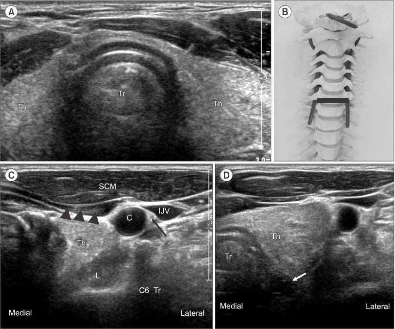
Figure 7 (A) Ultrasonography on anterior transverse scan at the level of cricoid cartilage shows thyroid gland (Th) in midline. (B) Position of probe for (A) on the artificial spine model. (C) By moving the ultrasound probe laterally until the carotid artery (C) can be seen, the 6th cervical transverse process (C6 Tr), carotid artery, internal jugular vein (IJV), vagus nerve (arrow), longus colli (L) omohyoid (arrowheads) and sternocleidomastoid muscle (SCM) are shown. (D) Esophagus (arrow) is seen behind the trachea (Tr).
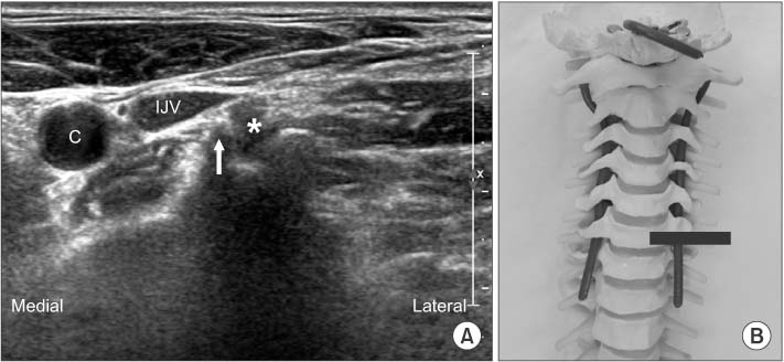
Figure 8 (A) Axial transverse image showing sharp anterior tubercle (white arrow) and posterior tubercle (black arrow) of C6 transverse process. Asterisk indicates exiting nerve root. (B) Position of probe for (A) on the artificial spine model. C, carotid artery; IJV, internal jugular vein.

Figure 9 Anterior scalene muscle (ASM) is deep to sternocleidomastoid muscle (SCM) and lateral to the internal jugular vein. Middle scalene (MSM) is found further postero-lateral. Between anterior and middle scalene muscle, visualize the roots or trunks of the brachial plexus (arrowheads) in the interscalene groove. These can appear as round or oval bundles with hypoechoic centers. C, carotid artery; C7 Tr, the 7th cervical transverse process.
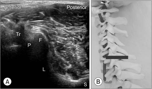
Figure 10 (A) Continue to move the probe posterolaterally around the neck. Posterior tubercle of C6 transverse process (Tr), pedicle (P), facet joint (F), lamina (L) and spinous process (S) can be seen. (B) Position of probe for (A) on the artificial spine model.

Figure 11 (A) C4 transverse process (C4 Tr) can be shown at the level of carotid artery bifurcation (arrows). (B) C5 transverse process (C5 Tr) is located at the level of upper thyroid gland and has similar size tubercles. (C) C6 transverse process is located at the level of lower thyroid gland and has a sharp, tall anterior tubercle (white arrow). Open arrow indicates low, round posterior tubercle and asterisk is C6 root. (D) Transverse sonogram at C7 vertebral level shows C7 root (asterisk) between vertebral artery (white arrow) and posterior tubercle (black arrow). Anterior tubercle is absent. Vertebral artery is confirmed by Doppler scan in the right side picture. (E) Anterior tubercle is absent and vertebral artery is exposed (arrow) at C7 vertebral level of artificial spine model. Th, thyroid gland.
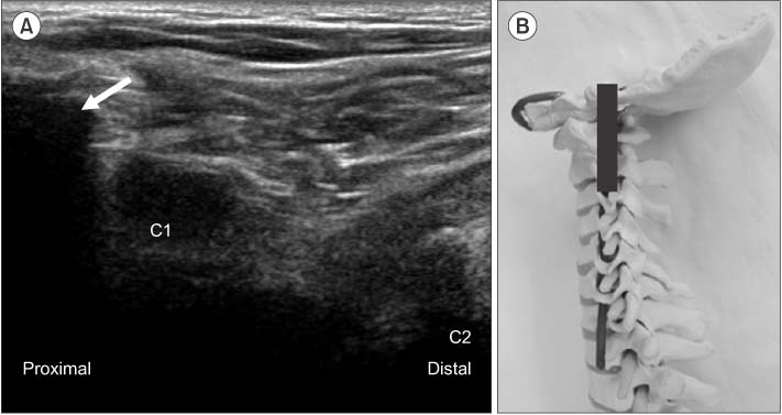
Figure 12 (A) Lateral longitudinal sonogram below the mastoid process (arrow) shows transverse processes of C1 (taller and wider) and C2. (B) Position of probe for (A) on the artificial spine model.
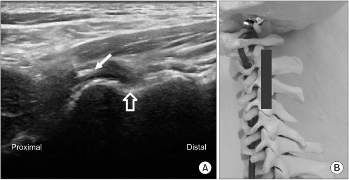
Figure 13 Lateral longitudinal sonogram at C2-3 level shows the 3rd occipital nerve (white arrow) crossing C2-3 joint and C3 medial branch (open arrow) at the waist of articular pillar. (B) Position of probe for (A) on the artificial spine model.

Figure 14 Doctor should wear mask and sterile gloves, and then sterilize cervical area with bethadine solution. Probe is enveloped by sterile vinyl after coverage with gel to minimize the risk of infection.

Figure 15 The influence of head rotation. (A) In neutral position of head, sternocleidomastoid muscle (SCM) overlay the root and plexus (arrows). (B) If the head is turned adequately to opposite side, the SCM moves to the medial side and does not overlay the root and plexus (arrows). C, carotid artery; Tr, transverse process.
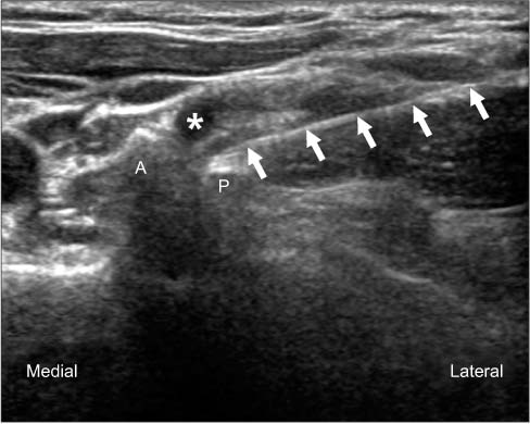
Figure 16 Solid arrows point to the needle in place at the posterior aspect of root during ultrasound-guided selective nerve root block. A, anterior tubercle of C6 transverse process; P, posterior tubercle of C6 transverse process; Asterisk, C6 root.

Figure 17 (A) Coronal longitudinal sonogram at the level of articular pillars. Medial branches (asterisks) are usually located at the deepest points between articulations. These points are target for out of plane technique. Arrows indicate entries of facet articular joints. (B) Needle (arrow) is inserted into the deepest points between articulations by out of plane technique. Needle is shown as a white spot on the groove. (C) Position of probe for (A) on the artificial spine model.
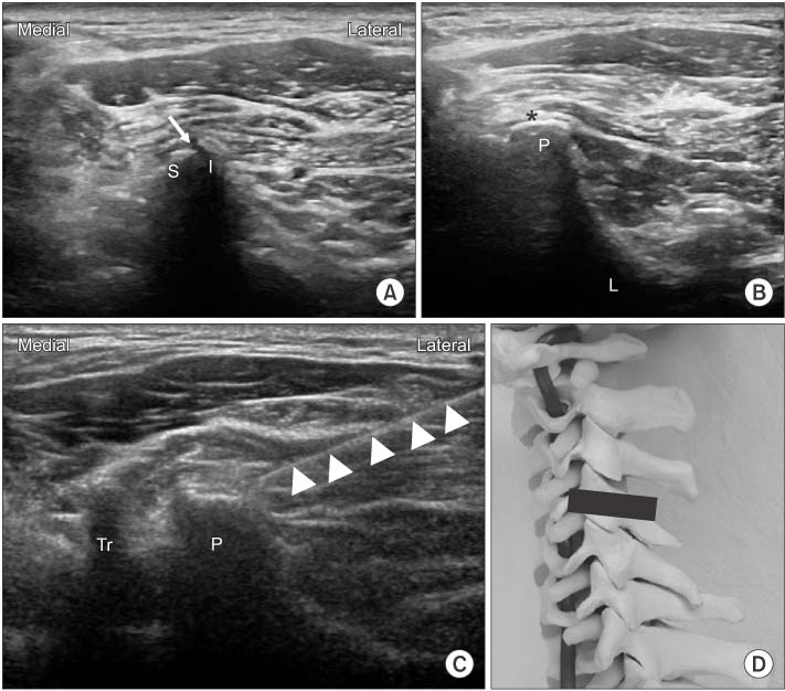
Figure 18 (A) Initially achieved transverse sonogram at the level of targeting facet joint. Arrow indicates entry of joint. (B) Moving probe to slight distally and proximally to obtain images of articular pillars on which medial branches run (asterisk). (C) 23 G, 6 cm needle (arrowheads) is introduced by use of real-time in-plane ultrasound guidance to target point for medial branch block. (D) Position of probe for (B) at artificial spine model. S, superior articular process of lower vertebra; I, inferior articular process of upper vertebra; P, articular pilla; L, lamina; Tr, transverse process.
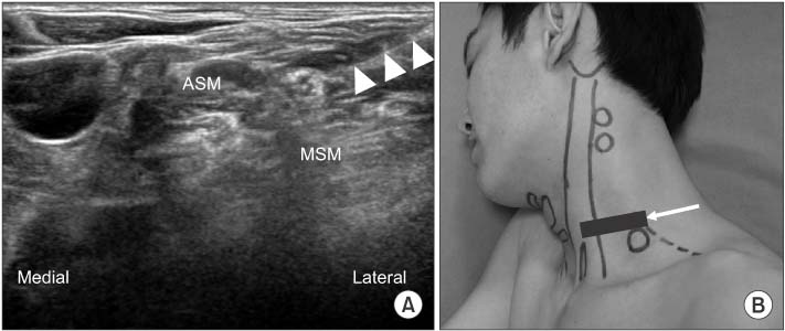
Figure 19 (A) In-plane approach from the posterior-lateral side of the probe for interscalene brachial plexus block. Needle (arrowheads) is inserted into interscalene groove at an angle of about 45 degrees to the skin surface. The needle tip is slowly advanced towards the plexus, avoiding any sensitive structures. Appropriate needle placement is confirmed by movement of the plexus with the flow of injectant and spread around the entire plexus. (B) Position of probe for (A). Arrow indicates the direction of the needle. ASM, anterior scalene muscle; MSM, middle scalene muscle.
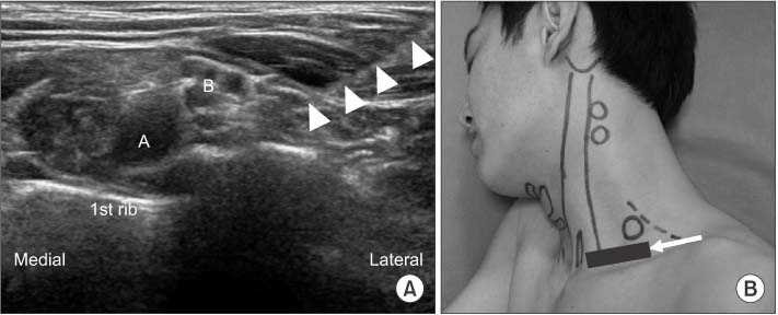
Figure 20 (A) Needle (arrowheads) is inserted and slowly advanced using lateral-to-medial orientation towards the deep border of the plexus where it meets the subclavian artery in supraclavicular brachial plexus block. (B) Position of probe for (A). Arrow indicates the direction of needle. A, subclavian artery; B, brachial plexus.
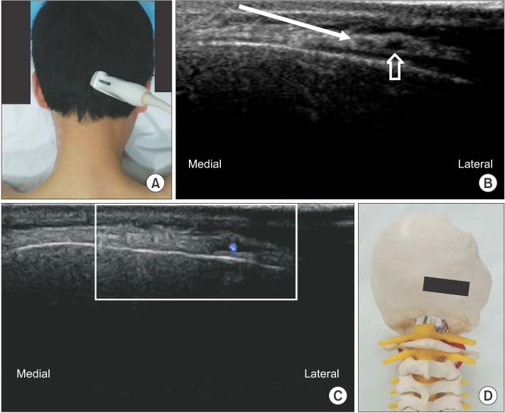
Figure 21 (A) Ultrasound probe is placed in transverse plane at the level of the medial superior nuchal line. (B) Moving probe from medial to lateral until occipital artery (open arrow) is found. By in-plane technique, insert needle from lateral to medial near the artery (arrow). (C) Occipital artery can be confirmed by Doppler scan. (D) Position of probe for (B) at artificial spine model.
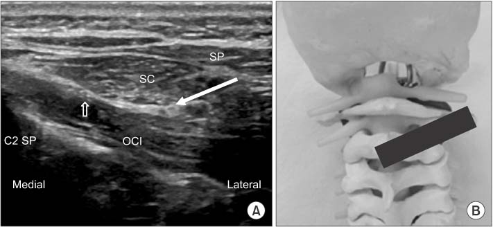
Figure 22 (A) Oblique transverse scan between C2 spinous process and C1 transverse process. Arrow indicates greater occipital nerve in the intermuscular plane between obliquus capitis inferior and semispinalis capitis and the direction of the needle for block. Open arrow indicates the 3rd occipital nerve. (B) Position of probe for (A) at artificial spine model. OCI, obliquus capitis inferior; SC, semispinalis capitis; SP, splenius capitis; C2 SP, spinous process of axis.
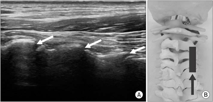
Figure 23 (A) Arrows indicate the direction of the needle by in-plane technique to enter facet joint in coronal longitudinal sonogram at the lateral aspect of neck. (B) Position of probe for (A) at artificial spine model. Arrow indicates the direction of needle to enter facet joint.

Figure 24 (A) Transverse scan of facet joint. Arrow indicates the direction of the needle to enter facet joint. (B) Position of probe for (A) at artificial spine model. Arrow indicates the direction of the needle to enter the facet joint.
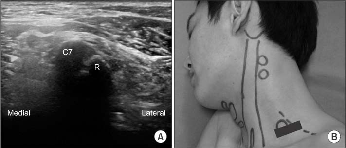
Figure 25 (A) Transverse scan at the base of neck. Transverse process of C7 and 1st rib (R) joins like a joint. This point can be a landmark to determine the facet joint level proximally. (B) Position of probe for (A). C7, transverse process of C7.
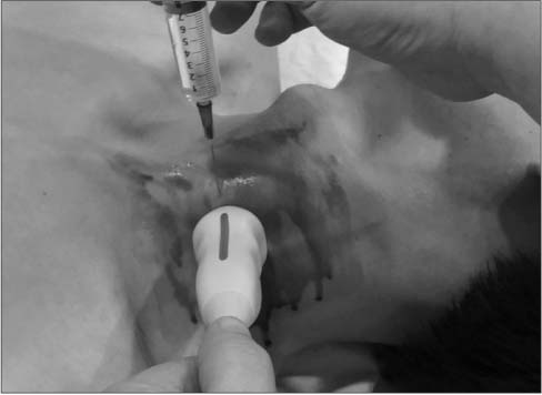
Figure 26 During stellate ganglion block, a small caliber probe like a Hockey stick probe is necessary. After compression by probe, the gap between thyroid and carotid artery will be widened and the depth from skin to ganglion can be diminished to make it easier to reach stellate ganglion. Needle is inserted almost perpendicular to skin.
Cited by 1 articles
-
Comparison of the Clinical Outcomes of an Ultrasound-Guided and C-Arm Guided Cervical Nerve Root Block
Dae Ho Ha, Dae Moo Shim, Tae Kyun Kim, Sung Kyun Oh, Hyun Jun Lee
J Korean Orthop Assoc. 2020;55(1):78-84. doi: 10.4055/jkoa.2020.55.1.78.
Reference
-
1. Rathmell JP, Aprill C, Bogduk N. Cervical transforaminal injection of steroids. Anesthesiology. 2004; 100:1595–1600.
Article2. Tiso RL, Cutler T, Catania JA, Whalen K. Adverse central nervous system sequelae after selective transforaminal block: the role of corticosteroids. Spine J. 2004; 4:468–474.3. Baker R, Dreyfuss P, Mercer S, Bogduk N. Cervical transforaminal injection of corticosteroids into a radicular artery: a possible mechanism for spinal cord injury. Pain. 2003; 103:211–215.
Article4. Provenzano DA, Fanciullo G. Cervical transforaminal epidural steroid injections: should we be performing them? Reg Anesth Pain Med. 2007; 32:168.
Article5. Scanlon GC, Moeller-Bertram T, Romanowsky SM, Wallace MS. Cervical transforaminal epidural steroid injections: more dangerous than we think? Spine (Phila Pa 1976). 2007; 32:1249–1256.6. Suresh S, Berman J, Connell DA. Cerebellar and brainstem infarction as a complication of CT-guided transforaminal cervical nerve root block. Skeletal Radiol. 2007; 36:449–452.
Article7. Moon SH. Ultrasound-guided intervention in cervical spine. J Korean Orthop US Soc. 2014; 1:49–66.8. Nakagawa M, Shinbori H, Ohseto K. Ultrasound-guided and fluoroscopy-assisted selective cervical nerve root blocks. Masui. 2009; 58:1506–1511.9. Narouze SN, Vydyanathan A, Kapural L, Sessler DI, Mekhail N. Ultrasound-guided cervical selective nerve root block: a fluoroscopy-controlled feasibility study. Reg Anesth Pain Med. 2009; 34:343–348.10. Razzaq AA, O'Brien D, Mathew B, Bartlett R, Taylor D. Efficacy and durability of fluoroscopically guided cervical nerve root block. Br J Neurosurg. 2007; 21:365–369.
Article11. Martin DC, Willis ML, Mullinax LA, Clarke NL, Homburger JA, Berger IH. Pulsed radiofrequency application in the treatment of chronic pain. Pain Pract. 2007; 7:31–35.
Article12. Anderberg L, Annertz M, Rydholm U, Brandt L, Säveland H. Selective diagnostic nerve root block for the evaluation of radicular pain in the multilevel degenerated cervical spine. Eur Spine J. 2006; 15:794–801.
Article13. Galiano K, Obwegeser AA, Bodner G, et al. Ultrasound-guided periradicular injections in the middle to lower cervical spine: an imaging study of a new approach. Reg Anesth Pain Med. 2005; 30:391–396.
Article14. Jee H, Lee JH, Kim J, Park KD, Lee WY, Park Y. Ultrasoundguided selective nerve root block versus fluoroscopy-guided transforaminal block for the treatment of radicular pain in the lower cervical spine: a randomized, blinded, controlled study. Skeletal Radiol. 2013; 42:69–78.
Article15. Yamauchi M, Suzuki D, Niiya T, et al. Ultrasound-guided cervical nerve root block: spread of solution and clinical effect. Pain Med. 2011; 12:1190–1195.
Article16. Manchikanti L, Singh V, Falco FJ, Cash KA, Fellows B. Comparative outcomes of a 2-year follow-up of cervical medial branch blocks in management of chronic neck pain: a randomized, double-blind controlled trial. Pain Physician. 2010; 13:437–450.17. Siegenthaler A, Mlekusch S, Trelle S, Schliessbach J, Curatolo M, Eichenberger U. Accuracy of ultrasound-guided nerve blocks of the cervical zygapophysial joints. Anesthesiology. 2012; 117:347–352.
Article18. Greher M, Moriggl B, Curatolo M, Kirchmair L, Eichenberger U. Sonographic visualization and ultrasound-guided blockade of the greater occipital nerve: a comparison of two selective techniques confirmed by anatomical dissection. Br J Anaesth. 2010; 104:637–642.
Article19. Loukas M, El-Sedfy A, Tubbs RS, et al. Identification of greater occipital nerve landmarks for the treatment of occipital neuralgia. Folia Morphol (Warsz). 2006; 65:337–342.20. Narouze SN, Provenzano DA. Sonographically guided cervical facet nerve and joint injections: why sonography? J Ultrasound Med. 2013; 32:1885–1896.21. Obernauer J, Galiano K, Gruber H, et al. Ultrasound-guided versus Computed Tomography-controlled facet joint injections in the middle and lower cervical spine: a prospective randomized clinical trial. Med Ultrason. 2013; 15:10–15.
Article
