CT-Based Essential Cardiac Anatomy for Radiology Residents to Understand Congenital Heart Disease
- Affiliations
-
- 1Department of Radiology, Asan Medical Center, University of Ulsan College of Medicine, Seoul, Korea. ghw68@hanmail.net
- KMID: 2464910
- DOI: http://doi.org/10.3348/jksr.2019.80.6.1107
Abstract
- Congenital heart disease is often associated with severe clinical presentations demanding prompt imaging diagnosis and appropriate treatment. Therefore, radiologists, particularly radiology residents, should be familiar with essential cardiac anatomy in order to diagnose congenital heart disease. In our clinical practice, cardiac anatomy is commonly depicted on CT images acquired with state-of-the art CT imaging techniques; however, the related imaging findings may be overlooked due to lack of attention, experience, or knowledge. It is partly due to the fact that CT-based illustration of cardiac anatomy to help understand congenital heart disease is currently scarce. In this article, cardiac imaging planes; crucial anatomical landmarks; morphological features of cardiac chambers, septa, and valves; and connections of cardiac segments are illustrated using cardiac CT images to facilitate understanding of congenital heart disease.
Figure
-

Fig. 1. Cardiovascular structures forming a cardiac silhouette on CT scout images. A. On anteroposterior CT scout image, the right cardiac silhouette is formed by the superior vena cava (1) and right atrium (2), and the left cardiac silhouette is formed by the aortic knob (3), pulmonary conus (4), leftatrial appendage (5), and LV (6). B. These cardiovascular structures (1–6) forming the right and left cardiac silhouettes are shown on the frontal volume-rendered CT image. C. On lateral CT scout image, the anterior and posterior cardiac silhouettes (dotted lines) are shown. D. Sagittal volume-rendered CT image shows that the anterior cardiac silhouette is formed by the RV and the posterior cardiac silhouette is formed by the LA and LV. The MPA arising from the RV is noted. LA = left atrium, LV = left ventricle, MPA = main pulmonary artery, RV = right ventricle

Fig. 2. Cardiac CT imaging planes. A. Frontal volume-rendered CT image showing the long axis of the heart. The long axis imaging planes (pink color) are parallel to that of the heart, while the short-axis imaging planes (blue color) are perpendicular to the long axisof the heart. B. A series of short-axis CT images from the base of the RV and LV to the cardiac apex. C. Horizontal and vertical long-axis images showing 4-, 3-, and 2-chamber views. LA = left atrium, LV = left ventricle, RA = right atrium, RV = right ventricle
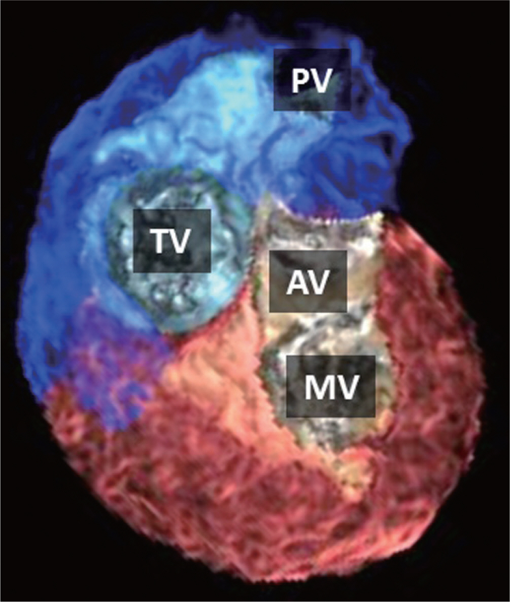
Fig. 3. Base of ventricles. Posterior and superior volume-rendered CT im-ages of both ventricles showing the spatial relationships between the left and right semilunar and atrioventricular valves. In contrast to the fibrous continuity between the AV and MV, a muscular right ventricular outflow tract is present between the PV and TV. AV = aortic valve, MV = mitral valve, PV = pulmonary valve, TV = tricuspid valve

Fig. 5. Comparison between conventional volume rendering and cinematic rendering techniques in a patient who underwent arterial switch operation for transposition of the great arteries. A-D. Compared with conventional volume-rendered cardiac CT images (A, B), cinematic rendering creates photorealistic images (C, D) by using a more complex lighting model. However, obscuration of some cardiovascular structures due to shadowing effects is a potential pitfall of cinematic rendering. The PT is anterior to the AA as a consequence of the LeCompte maneuver. The transferred right and left coronary arteries appear patent without significant stenosis. AA = ascending aorta, LV = left ventricle, PT = pulmonary trunk, RA = right atrium, RV = right ventricle
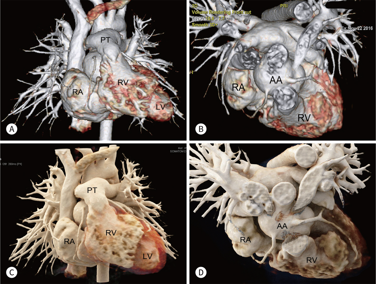
Fig. 6. Cardiac apex formed by the RV in a patient with double outlet RV and a small LV. A, B. Four-chamber cardiac CT image (A) and inferior volume-rendered cardiac CT image (B) show an enlargement of the RA and RV. In contrast, the LA and LV appear relatively small. A partial anomalous pulmonary venous connection (arrow), in which the right pulmonary vein is anomalously connected to the RA, is also noted. LA = left atrium, LV = left ventricle, RA = right atrium, RV = right ventricle

Fig. 7. Crux cordis. Inferior volume-rendered cardiac CT image shows crux cordis where the atrioventricular sulcus (blue dotted line) and the conjunc-tion (red dotted line) of the posterior interventricular sulcus and posterior interatrial sulcus cross each other. The cardiac apex (arrow) formed normally by the LV is also indicated. LV = left ventricle, RV = right ventricle
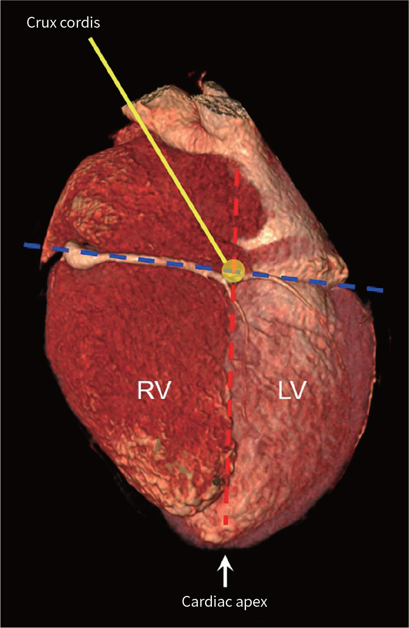
Fig. 8. Morphological features of the RA. A. Transparent volume-rendered cardiac CT image showing the pectinate muscles in both atria. The pectinate muscles in the dilated right atrial appendage extend to the right atrioventricular junction (asterisks), while those in the left atrial appendage do not extend to the left atrioventricular junction (arrows). B. Axial cardiac CT image showing the terminal sulcus (arrow) in a patient with Kawasaki disease and a right coronary artery aneurysm (asterisk). C. Transparent volume-rendered cardiac CT image showing the FO, an oval-shaped depression, in the septal surface of the RA. The septal surface of the RV is also seen. D. Short-axis cardiac CT image showing the coronary sinus (asterisks) draining into the RA. FO = fossa ovalis, LA = left atrium, RA = right atrium, RV = right ventricle

Fig. 9. Morphological features of the RV. A. Axial cardiac CT image showing the moderator band (arrows), a muscular band between the apical portion of the septomarginal trabecula and free wall of the RV around the base of the anterior papillary muscle. B. Transparent volume-rendered cardiac CT image showing the MPM (arrow) on the septal surface of the RV. C. Oblique coronal cardiac CT images demonstrate the inlet, trabecular, and outlet components of the RV. The VIF (dotted line) forms the superior septal margin of the supraventricular crest. The MPM (arrow) and PV (arrows) are noted. IVC = inferior vena cava, LA = left atrium, LV = left ventricle, MPM = medial papillary muscle, OS = outlet septum, PV = pulmonary valve, RA = right atrium, RV = right ventricle, RVOT = right ventricular outflow tract, SVC = superior vena cava, VIF = ventriculo-infundibular fold
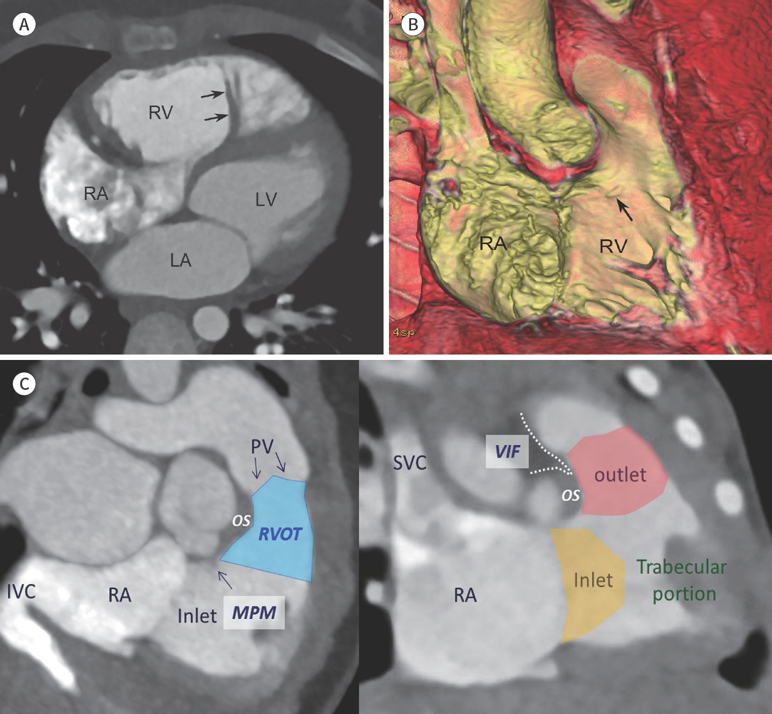
Fig. 10. Morphological features of the LV. Transparent volume-rendered cardiac CT image shows the ‘A' and ‘P' papillary muscles of the LV. A = anterolateral, LV = left ventricle, P = posteromedial
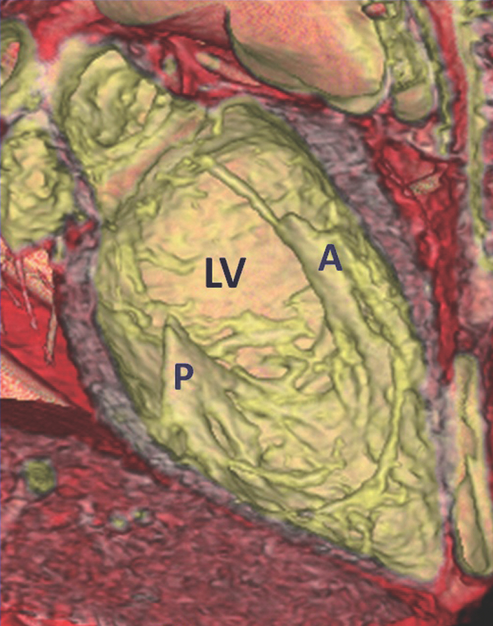
Fig. 11. Septum of the heart. A. Transparent volume-rendered cardiac CT image shows the cardiac septum viewed from the right heart, consisting of the IAS, AVS, and IVS. The AVS is produced by a septal offset between the tricuspid and mitral valves (two dotted lines). The ‘M' of the cardiac septum is located beneath the aortic valve between the rightand non-coronary aortic cusps. B. The AVS is illustrated on 4-chamber view. Notably, the septal attachment of the tricuspid valve (long arrow) is apically located, compared with that of the mitral valve (short arrow). The septal offset corresponds to the location of the AVS. AVS = atrioventricular septum, IAS = interatrial septum, IVS = interventricular septum, LA = left atrium, LV = left ventricle, M = membranous portion, RA = right atrium, RV = right ventricle
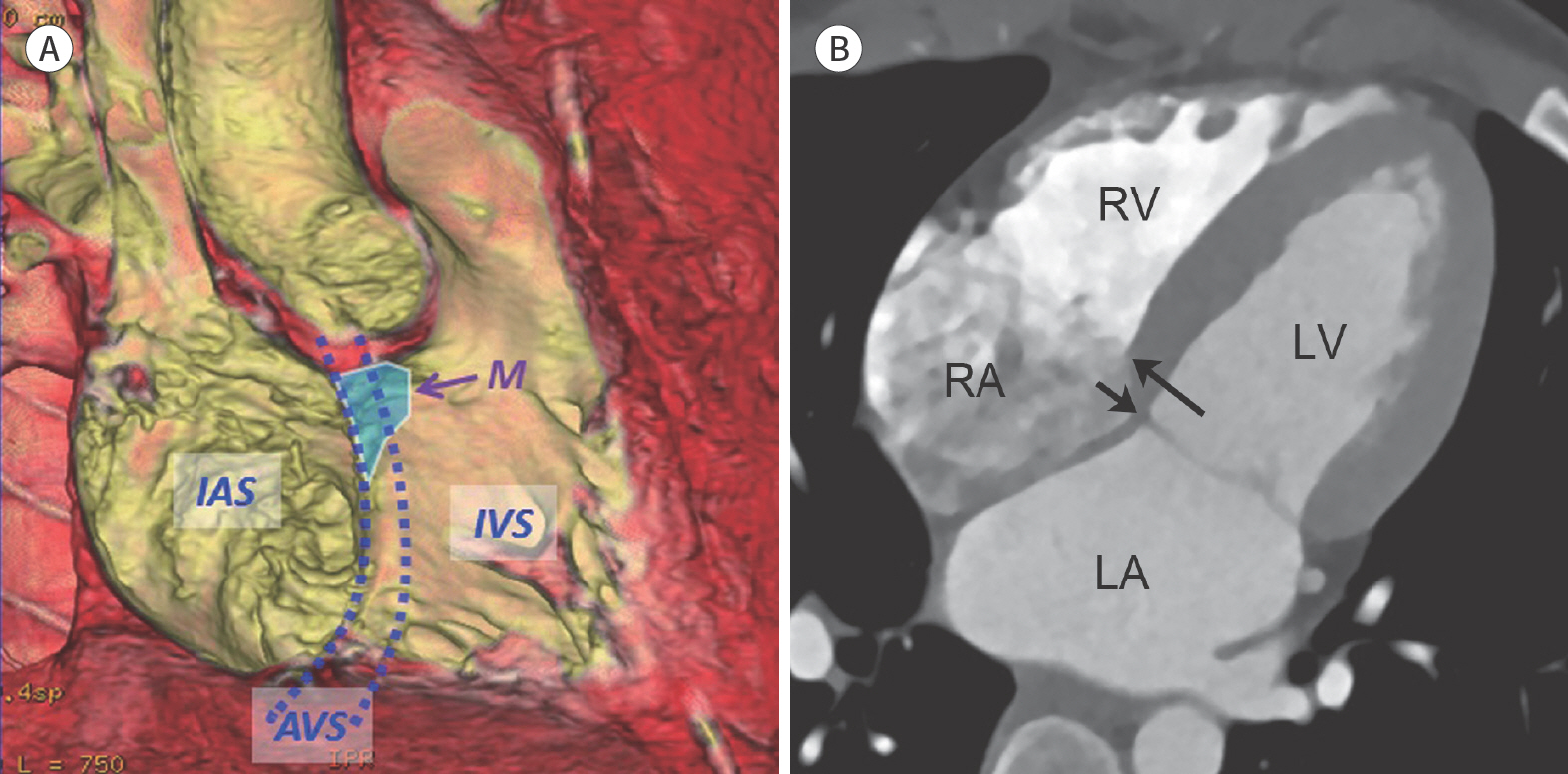
Fig. 12. Cardiac valves. A. Transparent volume-rendered cardiac CT image shows the L, R, and N aortic cusps as well as closed leaflets of the AV. The left main coronary artery (arrow) is noted. B. Transparent volume-rendered cardiac CT image shows closed A and P mitral leaflets. The AV is also seen. C. Oblique axial cardiac CT image shows the normal spatial relationship between the great arteries, in which the pulmonary artery is located anterior and left to the ascending aorta. In addition, the commissures (arrows) of the two F of the semilunar valves are generally aligned to each other. A = anterior, AV = aortic valve, F = facing sinuses, L = left, LA = left atrium, LVOT = left ventricular outflow tract, N = non-coronary, P = posterior, PT = pulmonary trunk, R = right, RA = right atrium

Fig. 13. Connections of cardiac segments. In pulmonary circulation (left image), the RA is connected to the RV and then to the PT. In systemic circulation (middle image), the left atrium is connected to the LV and then to the aA. A characteristic spiral relationship is observed between the right and left ventriculoarterial junctions (blue and red dotted arrows). aA = ascending aorta, LV = left ventricle, PT = pulmonary trunk, RA = right atrium, RV = right ventricle
Reference
-
References
1. Jang SY, Seo SR, Moon JR, Cho EJ, Kim E, Chang SA, et al. Prevalence and mortality of congenital heart disease in Korean adults.Medicine (Baltimore). 2018; 97:e11348.2. Suranyi P, Varga-Szemes A, Hlavacek AM. An overview of cardiac computed tomography in adults with congenital heart disease. J Thorac Imaging. 2017; 32:258–273.
Article3. De Cecco CN, Muscogiuri G, Madrid Pérez JM, Eid M, Suranyi P, Lesslie VW, et al. Pictorial review of surgical anatomy in adult congenital heart disease.J Thorac Imaging. 2017; 32:217–232.4. Goo HW, Park IS, Ko JK, Kim YH, Seo DM, Yun TJ, et al. CT of congenital heart disease: normal anatomy and typical pathologic conditions.Radiographics. 2003; 23:Spec No: S147-S165.5. Goo HW, Park IS, Ko JK, Kim YH, Seo DM, Park JJ. Computed tomography for the diagnosis of congenital heart disease in pediatric and adult patients. Int J Cardiovasc Imaging. 2005; 21:347–365. ; discussion 367.
Article6. Goo HW. State-of-the-art CT imaging techniques for congenital heart disease. Korean J Radiol. 2010; 11:4–18.
Article7. Goo HW, Yang DH. Coronary artery visibility in free-breathing young children with congenital heart disease on cardiac 64-slice CT: dual-source ECG-triggered sequential scan vs. single-source non-ECG-synchronized spiral scan. Pediatr Radiol. 2010; 40:1670–1680.
Article8. Goo HW. Cardiac MDCT in children: CT technology overview and interpretation.Radiol Clin North Am. 2011; 49:997–1010.9. Goo HW. Current trends in cardiac CT in children. Acta Radiol. 2013; 54:1055–1062.
Article10. Tsai IC, Goo HW. Cardiac CT and MRI for congenital heart disease in Asian countries: recent trends in publication based on a scientific database.Int J Cardiovasc Imag/iing. 2013; 29(Suppl 1):1–5.11. Bang JH, Park JJ, Goo HW. Evaluation of commissural malalignment of aortic-pulmonary sinus using cardiac CT for arterial switch operation: comparison with transthoracic echocardiography.Pediatr Rad/iiol. 2017; 47:556–564.12. Goo HW, Park SH. Pulmonary vascular volume ratio measured by cardiac computed tomography in children and young adults with congenital heart disease: comparison with lung perfusion scintigraphy. Ped/iiatr Radiol. 2017; 47:1580–1587.
Article13. Goo HW. Identification of coronary artery anatomy on dual-source cardiac computed tomography before arterial switch operation in newborns and young infants: comparison with transthoracic echocardiography.14. Goo HW. Coronary artery anomalies on preoperative cardiac CT in children with tetralogy of Fallot or Fallot type of double outlet right ventricle: comparison with surgical findings.Int J Cardiovasc Imaging. 2018; 34:1997–2009.15. Goo HW.CT in pediatric heart disease. In Saremi F, Achenbach S, Arbustini E, Narula J, eds. Revisiting cardiac anatomy: a computed-tomography-based atlas and reference. Boston: Wiley-Blackwell;2006. p. 76–84.16. Rowe SP, Johnson PT, Fishman EK. Cinematic rendering of cardiac CT volumetric data: principles and initial observations.J Cardiovasc Comput Tomogr. 2018; 12:56–59.17. Mori S, Fukuzawa K, Takaya T, Takamine S, Ito T, Fujiwara S, et al. Clinical cardiac structural anatomy reconstructed within the cardiac contour using multidetector-row computed tomography: atrial septum and.18. Saremi F, Ho SY, Cabrera JA, Sánchez-Quintana D. Right ventricular outflow tract imaging with CT and MRI: part 1, morphology.AJR Am J Roentgenol. 2013; 200:W39–W50.19. Mori S, Fukuzawa K, Takaya T, Takamine S, Ito T, Fujiwara S, et al. Clinical cardiac structural anatomy reconstructed within the cardiac contour using multidetector-row computed tomography: the arrangement and location of the cardiac valves. Clin Anat. 2016; 29:364–370.
Article
- Full Text Links
-
- Actions
-
Cited
- CITED
-
- Close
- Share
-
- Similar articles
-
- Double Outlet Right Ventricle: In-Depth Anatomic Review Using Three-Dimensional Cardiac CT Data
- Pattern Analysis of Left Ventricular Remodeling Using Cardiac Computed Tomography in Children with Congenital Heart Disease: Preliminary Results
- State-of-the-Art CT Imaging Techniques for Congenital Heart Disease
- MR Imaging of Congenital Heart Disease
- Congenital Anomalies of the Coronary Sinus: A Pictorial Essay
