Dose-Decreasing Effect of the First Reversed Laser Beam Collimator for C-Arm Type Angiographic Equipment
- Affiliations
-
- 1Department of Radiologic Science, College of Health Science, Eulji University, Seongnam, Korea. handk3113@naver.com
- 2Department of Radiological Technology, Ansan University, Ansan, Korea.
- KMID: 2379601
- DOI: http://doi.org/10.3346/jkms.2017.32.7.1083
Abstract
- This is a study on the dose-decreasing effect of the first reversed laser beam collimator (RLBC) for C-arm type angiographic equipment. A laser beam was located at the center of each plane at an oblique angle to the angiographic equipment detector. A field of view, which could be seen with the naked eye, was made by focusing the laser beam in the direction of the X-ray source. The height of the table was fixed at 75 cm and the iron balls were located within 2 mm of the top, bottom, left, and right edges of the output image. The time needed for location fixing, fluoroscopy, and measurement of dose area product (DAP) were compared by having 30 radiologists perform location fixing by looking at the fluoroscopic image while performing location fixing (no radiation) and while the RLBC was turned on. In the next test, the time needed for location fixing, fluoroscopy, and DAP were compared when varying the location of the iron balls from 2 to 10 mm from the edges of the output image. The results showed that the time needed for location fixing, the time needed for fluoroscopy, and DAP decreased, both in the first test and the second test. This study confirmed that the use of a RLBC for C-arm type angiographic equipment decreases both the time needed to perform the procedure and the radiation dose received. It is expected that continuous advancement of RLBC technology will contribute greatly to decreasing the dose of radiation needed and improving convenience during angiography.
Keyword
MeSH Terms
Figure
-
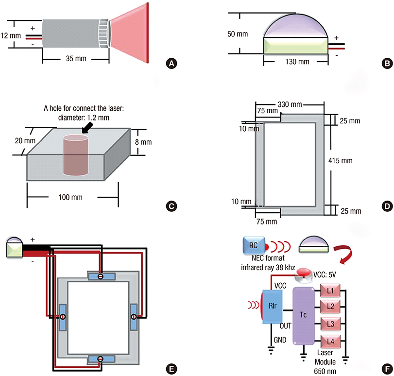
Fig. 1 A schematic diagram of RLBC. (A) Red line laser diode module. (B) The domed plastic container housing the timer chip and infrared ray receiving device, the timer chip, and 4 laser diode modules are connected. (C) Polystyrene laser diode module fixing device. (D) The acryl panel to be combined with the detector. (E) The arrangement of the parts viewed from the bottom. (F) A mimetic diagram of RLBC operation. An NEC format infrared ray with 38 kHz is operated by a remote control. The infrared rays are received by the RIR, the infrared ray receiving device, and 5 V power source. Then, the 4 diode modules at the Tc run for 10 seconds. RLBC = reversed laser beam collimator, NEC = National Electrical Code, RIR = received infrared ray, Tc = timer chip.
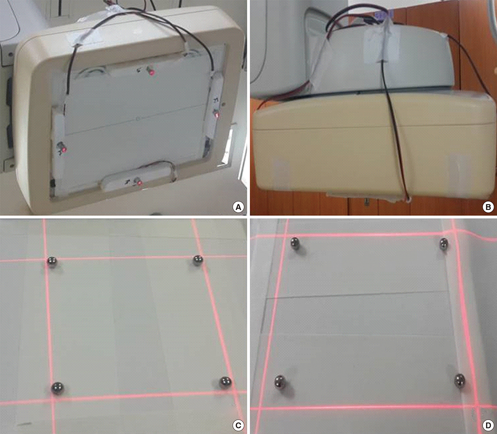
Fig. 2 The RLBC mounted on the instrument. (A) The detector with RLBC as seen from the bottom. (B) Seen from the side. (C) The field confirmed by RLBC after locating the iron balls within 2 mm. (D) The field confirmed by RLBC after locating the iron balls within 10 mm. RLBC = reversed laser beam collimator.
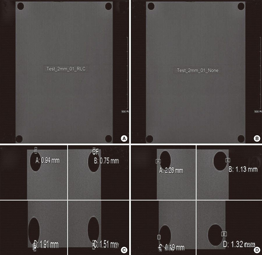
Fig. 3 RLBC in the test with the iron balls within 2 mm from the edges of image field. (A) The image of the fixed location without using the RLBC in the test with the iron balls within 2 mm from the edges of image field. (B) The image of the fixed location when using the RLBC. (C) and (D) Confirmation that the iron balls are within 2 mm from the edges of the image field. RLBC = reversed laser beam collimator.
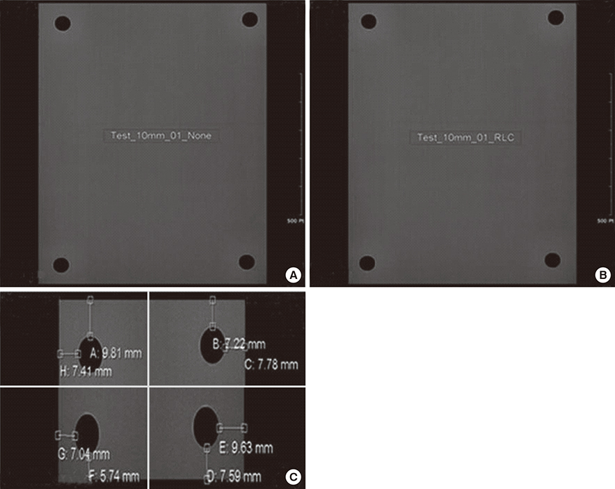
Fig. 4 RLBC in the test with the iron balls within 10 mm from the edges of image field. (A) The image of the fixed location without using the RLBC in the test with the iron balls within 10 mm from the edges of the image field. (B) The image of the fixed location when using the RLBC. (C) Confirmation that the iron balls are within 10 mm of the edges of the image field. RLBC = reversed laser beam collimator.
Reference
-
1. Venkatesan AM, Kundu S, Sacks D, Wallace MJ, Wojak JC, Rose SC, Clark TW, d’Othee BJ, Itkin M, Jones RS, et al. Practice guidelines for adult antibiotic prophylaxis during vascular and interventional radiology procedures. J Vasc Interv Radiol. 2010; 21:1611–1630.2. Söder HK, Manninen HI, Jaakkola P, Matsi PJ, Räsänen HT, Kaukanen E, Loponen P, Soimakallio S. Prospective trial of infrapopliteal artery balloon angioplasty for critical limb ischemia: angiographic and clinical results. J Vasc Interv Radiol. 2000; 11:1021–1031.3. Higashida RT, Tsai FY, Halbach VV, Dowd CF, Smith T, Fraser K, Hieshima GB. Transluminal angioplasty for atherosclerotic disease of the vertebral and basilar arteries. J Neurosurg. 1993; 78:192–198.4. Wholey MH, Wholey M, Bergeron P, Diethrich EB, Henry M, Laborde JC, Mathias K, Myla S, Roubin GS, Shawl F, et al. Current global status of carotid artery stent placement. Cathet Cardiovasc Diagn. 1998; 44:1–6.5. Rastan A, Krankenberg H, Baumgartner I, Blessing E, Müller-Hülsbeck S, Pilger E, Scheinert D, Lammer J, Beschorner U, Noory E, et al. Stent placement vs. balloon angioplasty for popliteal artery treatment: two-year results of a prospective, multicenter, randomized trial. J Endovasc Ther. 2015; 22:22–27.6. Byrne JV, Sohn MJ, Molyneux AJ, Chir B. Five-year experience in using coil embolization for ruptured intracranial aneurysms: outcomes and incidence of late rebleeding. J Neurosurg. 1999; 90:656–663.7. Massi F, Muretti M, Coradduzza E, Poddighe C, Terrosu P, Portoghese M. Myocardial infarction and rupture after bronchial artery embolization. Ann Thorac Surg. 2015; 99:1051–1053.8. Sakaguchi I, Ohba T, Ikeda O, Yamashita Y, Katabuchi H. Embolization for post-partum rupture of ovarian artery aneurysm: case report and review. J Obstet Gynaecol Res. 2015; 41:623–627.9. Yaacob Y, Nguyen DV, Mohamed Z, Ralib AR, Zakaria R, Muda S. Image-guided chemoport insertion by interventional radiologists: a single-center experience on periprocedural complications. Indian J Radiol Imaging. 2013; 23:121–125.10. Ahn SJ, Kim HC, Chung JW, An SB, Yin YH, Jae HJ, Park JH. Ultrasound and fluoroscopy-guided placement of central venous ports via internal jugular vein: retrospective analysis of 1254 port implantations at a single center. Korean J Radiol. 2012; 13:314–323.11. Song WG, Jin GY, Han YM, Yu HC. Central venous catheterization: comparison between interventional radiological procedure and blind surgical procedure. J Korean Radiol Soc. 2002; 47:467–472.12. Balter S, Hopewell JW, Miller DL, Wagner LK, Zelefsky MJ. Fluoroscopically guided interventional procedures: a review of radiation effects on patients’ skin and hair. Radiology. 2010; 254:326–341.13. Valentin J. Avoidance of radiation injuries from medical interventional procedures. Ann ICRP. 2000; 30:7–67.14. Koenig TR, Mettler FA, Wagner LK. Skin injuries from fluoroscopically guided procedures: part 2, review of 73 cases and recommendations for minimizing dose delivered to patient. AJR Am J Roentgenol. 2001; 177:13–20.15. Bor D, Sancak T, Olgar T, Elcim Y, Adanali A, Sanlidilek U, Akyar S. Comparison of effective doses obtained from dose-area product and air kerma measurements in interventional radiology. Br J Radiol. 2004; 77:315–322.16. Hwang JS, Hyun MK, Lee HJ, Choi JE, Kim JH, Lee NR, Kwon JW, Lee E. Endovascular coiling versus neurosurgical clipping in patients with unruptured intracranial aneurysm: a systematic review. BMC Neurol. 2012; 12:99.17. Qureshi AI, Suri MF, Khan J, Kim SH, Fessler RD, Ringer AJ, Guterman LR, Hopkins LN. Endovascular treatment of intracranial aneurysms by using Guglielmi detachable coils in awake patients: safety and feasibility. J Neurosurg. 2001; 94:880–885.18. Koenig TR, Wolff D, Mettler FA, Wagner LK. Skin injuries from fluoroscopically guided procedures: part 1, characteristics of radiation injury. AJR Am J Roentgenol. 2001; 177:3–11.19. Klein LW, Miller DL, Balter S, Laskey W, Haines D, Norbash A, Mauro MA, Goldstein JA; Joint Inter-Society Task Force on Occupational Hazards in the Interventional Laboratory. Occupational health hazards in the interventional laboratory: time for a safer environment. Catheter Cardiovasc Interv. 2009; 73:432–438.20. Sanchez R, Vano E, Fernandez JM, Gallego JJ. Staff radiation doses in a real-time display inside the angiography room. Cardiovasc Intervent Radiol. 2010; 33:1210–1214.21. Vano E, Ubeda C, Leyton F, Miranda P, Gonzalez L. Staff radiation doses in interventional cardiology: correlation with patient exposure. Pediatr Cardiol. 2009; 30:409–413.22. Roguin A, Goldstein J, Bar O. Brain tumours among interventional cardiologists: a cause for alarm? Report of four new cases from two cities and a review of the literature. EuroIntervention. 2012; 7:1081–1086.23. Hernandez RJ, Goodsitt MM. Reduction of radiation dose in pediatric patients using pulsed fluoroscopy. AJR Am J Roentgenol. 1996; 167:1247–1253.24. Faulkner K. Radiation protection in interventional radiology. Br J Radiol. 1997; 70:325–326.
- Full Text Links
-
- Actions
-
Cited
- CITED
-
- Close
- Share
-
- Similar articles
-
- Field size and dose distribution of electron beam
- A study on dose distribution of small irradiation field in the electron therapy
- Development of 250 picosecond Nd:YAG laser for dermatologic applications in Republic of Korea: development report
- Effect of Saline-Filled or Viscous Lidocaine-Filled Cuff on the Laser-Induced Polyvinyl Chloride Endotracheal Tube Fires and Tidal Volume
- Verification of Dose Distribution for Stereotactic Radiosurgery with a Linear Accelerator
