A 3-dimensional finite element analysis of tapered internal connection implant system (Avana SS III(R)) on different abutment connections
- Affiliations
-
- 1Department of Implant Dentistry, Graduate School of Clinical Dentistry, Ewha Womans University, Seoul, Korea. jseok2@hanmail.net
- 2Department of Esthetic Restorative Dentistry, Graduate School of Clinical Dentistry, Ewha Womans University, Seoul, Korea.
- 3Department of Dentistry, School of Medicine, Ewha Womans University, Seoul, Korea.
- KMID: 2195553
- DOI: http://doi.org/10.4047/jkap.2010.48.3.181
Abstract
- PURPOSE
The purpose of this study was to compare the stress distribution characteristics of four different abutment connections on SS-III(R) fixture under occlusal loading, using 3-dimensional finite element method.
MATERIALS AND METHODS
The fixture of SS-III(R) (Osstem, Korea) with 4 mm diameter and 11.5 mm length and 4 types of abutments were analyzed; Solid, Com-Octa, ComOcta Gold, and Octa abutment. The models were placed in the area of first molar in the mandible. The 4 loading conditions were; (1) the vertical loading of 100 N on the central fossa, (2) the vertical loading of 100 N on the buccal cusp, (3) the 30degreesinclined loading of 100 N to lingual side on the central fossa, and (4) the 30degrees inclined loading of 100 N to the lingual side on the buccal cusp. The 3G.Author program was used, the von-Mises stress was calculated and the stress contours were plotted on each part of the implant systems and the surrounding bone structures.
RESULTS
Regardless of abutment types and loading conditions, higher stress concentration was observed at the cortical bone. In cancellous bone, the highest stress was observed at apical portion and the maximum stress occurred at the implant neck. The higher internal stress was observed in the fixtures than in the bone. The lowest stress was observed at loading condition 1 and the stress concentration was also lower than any other loading conditions.
CONCLUSION
Within the limitation of the result of this study, it seems that the abutment connection type does not affect much on the stress distribution of bone structure.
MeSH Terms
Figure
-
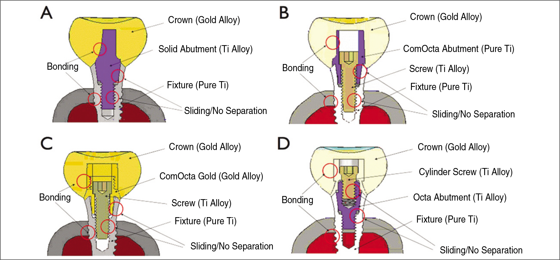
Fig. 1. Boundary conditions and materials of Model 1 (A: Solid abutment), Model 2 (B: ComOcta abutment), Model 3 (C: ComOcta Gold abutment) and Model 4 (D: Octa abutment).

Fig. 2. Locations and directions of loadings.

Fig. 3. Stress concentration in superstructure (Model 1).

Fig. 4. Maximum von-Mises stress in crown.

Fig. 5. Stress concentration in abutment screws (Load 3).
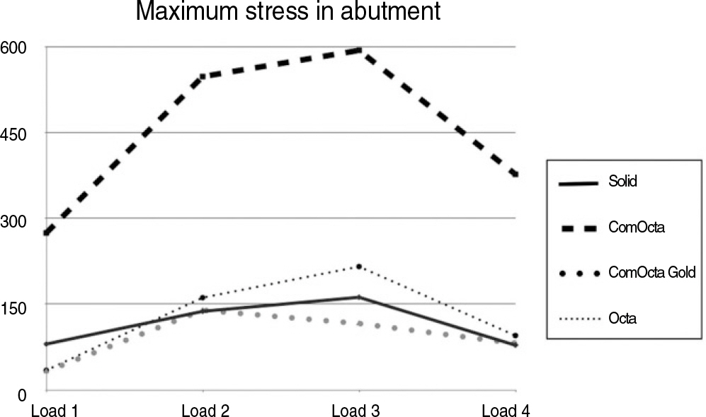
Fig. 6. Maximum von-Mises stress in abutment screw.

Fig. 7. Stress distribution in fixture.

Fig. 8. Maximum von-Mises stress in fixture.
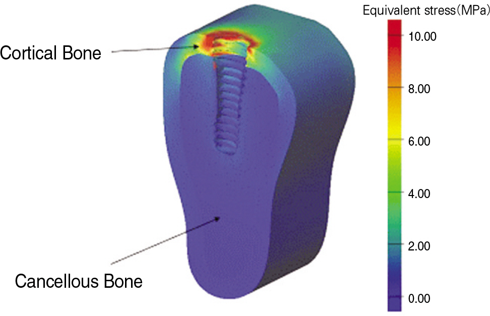
Fig. 9. Stress distributions in bone.
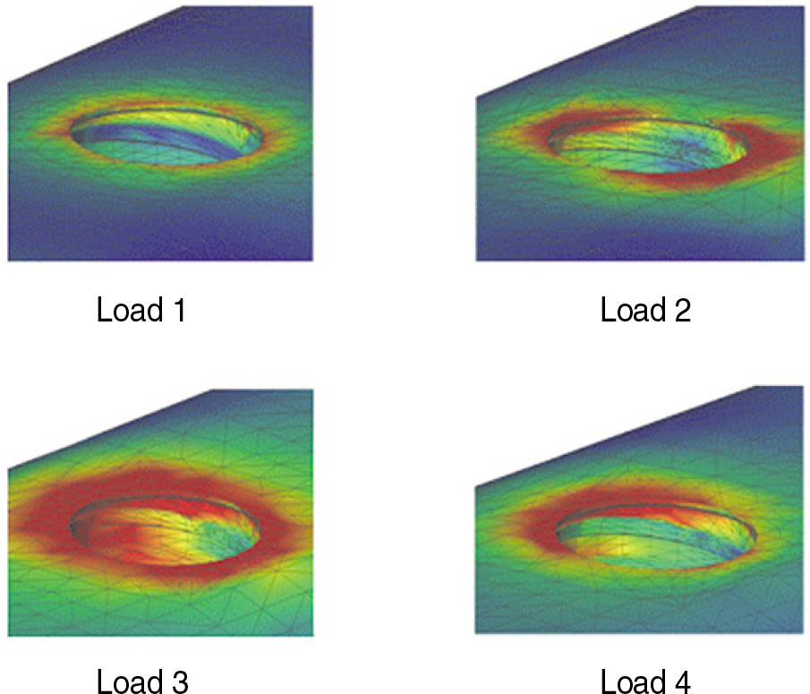
Fig. 10. Stress distribution in cortical bone under loading conditions (Model 4).
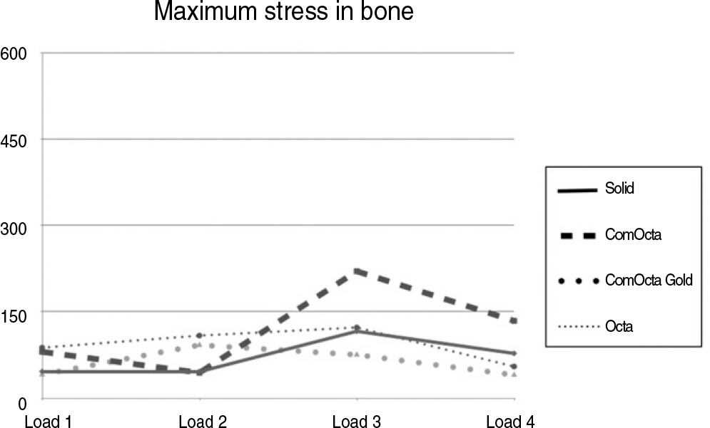
Fig. 11. Maximum von-Mises stress in bone.
Cited by 1 articles
-
Finite element analysis on the connection types of abutment and fixture
Byeong-Hyeon Jung, Gyeong-Je Lee, Dong-Wan Kang
J Korean Acad Prosthodont. 2012;50(2):119-127. doi: 10.4047/jkap.2012.50.2.119.
Reference
-
1.Bra � nemark PI., Zarb GA., Albrektsson T., Rosen H. Tissue-integrated prostheses. Osseointegration in clinical dentistry. Plast Reconstr Surg. 1986. 77:496–7.2.Han SU., Park HO., Yang HS. Stress analysis of supporting tissues and implants according to implant fixture shapes and implant-abutment connections. J Korean Acad Prosthodont. 2004. 42:226–37.3.Park WH., Lee YS. Three dimensional finite element stress analysis of implant prosthesis according to the different fixture locations and angulations. J Korean Acad Prosthodont. 2005. 43:61–77.4.Lee JM., Kim YS., Kim CH., Kim YH. 3-D FEA of three different single tooth abutments: Cement-retained vs Screw-retained. J Korean Acad Prosthodont. 1999. 37:269–88.5.Khraisat A., Stegaroiu R., Nomura S., Miyakawa O. Fatigue resistance of two implant/abutment joint designs. J Prosthet Dent. 2002. 88:604–10.
Article6.Naert IE., Duyck JA., Hosny MM., van Steenberghe D. Freestanding and tooth-implant connected prostheses in the treatment of partially edentulous patients. Part 1: An up to 15-years clinical evaluation. Clin Oral Implants Res. 2001. 12:237–44.7.Rangert B., Krogh PH., Langer B., Van Roekel N. Bending overload and implant fracture: A retrospective clinical analysis. Int J Oral Maxillofac Implants. 1995. 10:326–34.8.Shin HS., Chun HJ., Han CH., Lee SH. Three-dimensional stress analysis of implant systems in the mandibular bone with various abutment types and loading conditions. J Korean Acad Prosthodont. 2003. 41:617–25.9.Norton MR. An in vitro evaluation of the strength of an internal conical interface compared to a butt joint interface in implant design. Clin Oral Implants Res. 1997. 8:290–8.
Article10.Norton MR. Assessment of cold welding properties of the internal conical interface of two commercially available implant systems. J Prosthet Dent. 1999. 81:159–66.
Article11.Norton MR. An in vitro evaluation of the strength of a 1-piece and 2-piece conical abutment joint in implant design. Clin Oral Implants Res. 2000. 11:458–64.
Article12.Ahn JK., Kay KS., Chung CH. Finite element stress analysis of implant prosthesis with internal connection between the implant and the abutment. J Korean Acad Prosthodont. 2004. 42:356–72.13.Sutter F., Schroeder A., Buser DA. The new concept of ITI hollow-cylinder and hollow-screw implants: Part 1. Engineering and design. Int J Oral Maxillofac Implants. 1988. 3:161–72.14.Sutter F., Weber HP., Sorensen J., Belser U. The new restorative concept of the ITI Dental Implant System: design and engineering. Int J Periodontics Restorative Dent. 1993. 13:409–31.15.Moon BH., Yang JH. A study on the stress analysis of three rootform implants with finite element analysis. J Korean Acad Prosthodont. 1993. 31:129–50.16.Richter EJ. In vivo vertical forces on implants. Int J Oral Maxillofac Implants. 1995. 10:99–108.17.Rangert BR., Sullivan RM., Jemt TM. Load factor control for implants in the posterior partially edentulous segment. Int J Oral Maxillofac Implants. 1997. 12:360–70.18.Matsushita Y., Kitoh M., Mizuta K., Ikeda H., Suetsugu T. Two dimensional FEM analysis of hydroxyapatite implants: diameter effects on stress distribution. J Oral Implantol. 1990. 16:6–11.19.Lum LB., Osier JF. Load transfer from endosteal implants to supporting bone: an analysis using statics. Part one: Horizontal loading. J Oral Implantol. 1992. 18:343–8.20.Chung KM., Chung CH., Jeong SM. Finite element stress analysis of implant prosthesis according to platform width of fixture. J Korean Acad Prosthodont. 2003. 41:674–88.21.Andersson B., O¨dman P., Boss A., Jo ¨ rne ′us L. Mechanical testing of superstructures on the CeraOne abutment in the Bra � nemark system. Int J Oral Maxillofac Implants. 1994. 9:665–72.22.Kwon JH., Choi MH., Kim YL., Cho HW. Three-dimensional finite element stress analysis of single implant restoration using different fixture and abutment screw diameters. J Korean Acad Prosthodont. 2005. 43:105–19.
- Full Text Links
-
- Actions
-
Cited
- CITED
-
- Close
- Share
-
- Similar articles
-
- A study on the various implant systems using the finite element stress analysis
- Finite element stress analysis of implant prosthesis according to connection types of implant-abutment
- Finite element stress analysis of implant prosthesis with internal connection between the implant and the abutment
- Stress analysis of supporting tissues and implants according to implant fixture shapes and implant-abutment connections
- Fit of fixture/abutment interface of internal connection implant system
