Three-dimensional Effect of the Single Plane Proximal Femur Osteotomy
- Affiliations
-
- 1Department of Orthopedic Surgery, Dong-A University School of Medicine, Busan, Korea. sskim2@dau.ac.kr
- KMID: 2156016
- DOI: http://doi.org/10.5371/hp.2015.27.1.23
Abstract
- PURPOSE
Three-dimensional (3D) effects of the single plane osteotomies of the proximal femur are compared and analyzed by the trigonometric method.
MATERIALS AND METHODS
The shape of proximal femur was simplified as a bent line. The bent line is the continuation of the three points-the center of the femoral head, the center of femoral neck at the base, and the center of the femoral shaft. Then rotated the proximal femur at the junction of the neck and shaft with the each rotation axis of X, Y, Z, defined the frontal plane as a XY plane, sagittal plane as a YZ plane, and transverse plane as a XZ plane.
RESULTS
The varus osteotomy of the proximal femur in the frontal plane with the rotation axis 'Z' that meant the increase of the X coordinate and the decrease of Y coordinate with constant Z coordinate (Deltax>Deltay, Deltaz=0) resulted in decreased anteversion in the transverse plane and increased flexion in the sagittal plane. The derotation osteotomy (Deltax>Deltaz, Deltay=0) resulted in varus in the frontal plane and extension in the sagittal plane. The flexion osteotomy (Deltaz>Deltay, Deltax=0) resulted in increased anteversion in the transverse plane and varus in the frontal plane.
CONCLUSION
Single plane osteotomy for the proximal femur results in the angular correction in all three planes and may have the similar 3D effect of the certain double or triple osteotomy. So single plane osteotomy could be enough to correct some complex deformities.
Figure
-
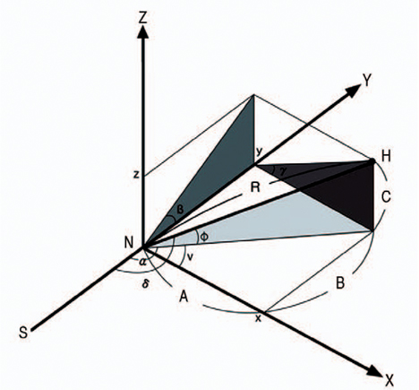
Fig. 1 Schematic drawing of right proximal femur in bent lines. H: the center of the femoral head, N: the center of femoral neck at the base, S: the center of the femoral shaft, R: the length of the femoral neck (true head-neck distance), Y axis: the extension of the center of the femoral shaft, X axis: the vertical to Y axis in the frontal plane at the junction of femoral neck and the shaft, Z axis: the vertical to Y axis in the sagittal plane at the junction of femoral neck and the shaft. So XY plane is frontal, YZ is sagittal, and XZ is transverse plane. The angle of femoral neck at XY, YZ and XZ plane has the value of α,β and γ respectively. Angle α is angle v plus 90, and angle v is valgus angle of femoral neck. Angle β is flexion angle and angle γ is anteversion angle of the femoral neck. The center of femoral head (H) is located in three-dimensional space and it has three coordinates of x, y, and z. A, B and C is the each value of x, y and z coordinate of the center of femoral head. Angle 'ϕ' is neck-frontal plane angle, and angle δ is true neck-shaft angle.
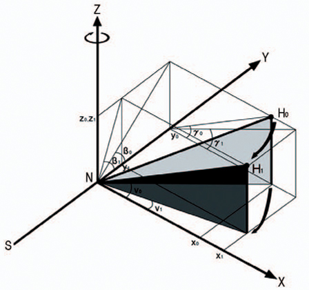
Fig. 2 With the rotation axis Z, varus osteotomy results in the change of three-dimensional location of femoral head. X coordinate is increased (x0
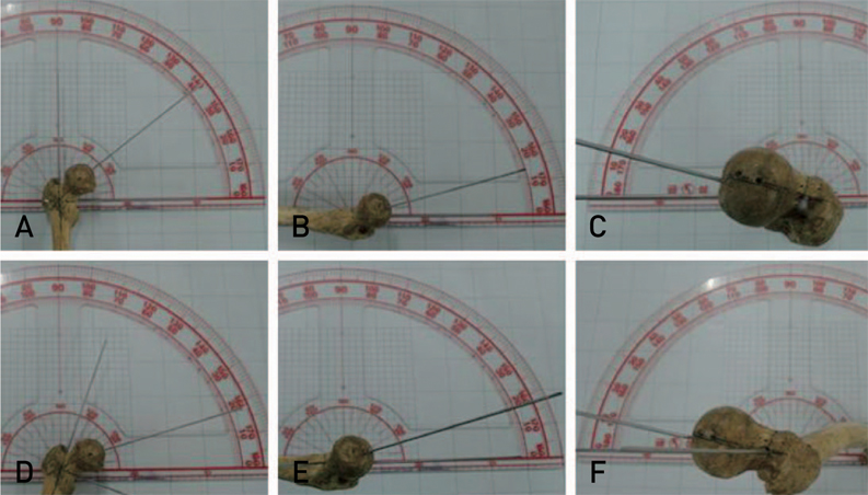
Fig. 3 Three-dimensional neck-shaft angle of real bone models with neutral and 20° varus rotation position. A neutral position shows frontal neck-shaft angle of 128° (A), sagittal neck-shaft angle of 15° (B), and transverse neck-shaft angle of 14° (C). With 20° varus rotation in the frontal plane, shows the change of the frontal neck-shaft angle to 108° (D), sagittal neck-shaft angle to 17° (E), and transverse neck-shaft angle of 10° (F).
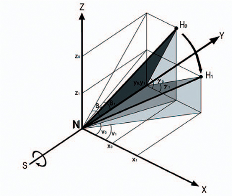
Fig. 4 Derotation (γ0>γ1) osteotomy with the rotation axis Y results in varus change (v0>v1) and decreased flexion (β0>β1) of femoral head. X coordinate is increased (x0
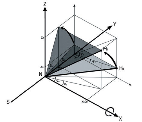
Fig. 5 Flexion (β0<β1) osteotomy with the rotation axis X results in varus change (v0>v1) and increased anteversion (γ0<γ1) of femoral head. Z coordinate is increased (z0
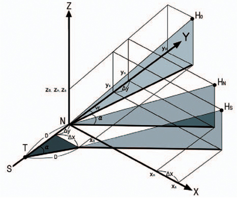
Fig. 6 The subtrochanteric varus osteotomy results in both increased change of ΔX and ΔY coordinates compared with varus osteotomy at the neck shaft junction. D: the distance between the base of neck and the level of subtrochanteric osteotomy, T: the level of subtrochanteric osteotomy, α: angle of varus correction, vr: varus angle of femoral neck before osteotomy. x0, y0, z0: x, y, z coordinates before osteotomy. xn, yn, zn: x, y, z coordinates after varus osteotomy at the neck shaft junction. xs, ys, zs: x, y, z coordinates after varus osteotomy at the subtrochanteric level.
Reference
-
1. Abel MF, Sutherland DH, Wenger DR, Mubarak SJ. Evaluation of CT scans and 3-D reformatted images for quantitative assessment of the hip. J Pediatr Orthop. 1994; 14:48–53.
Article2. Kane TJ, Henry G, Furry D. A simple roentgenographic measurement of femoral anteversion. A short note. J Bone Joint Surg Am. 1992; 74:1540–1542.
Article3. Howell FR, Newman RJ, Wang HL, Nevelo¨s AB, Dickson RA. The three-dimensional anatomy of the proximal femur in Perthes’ disease. J Bone Joint Surg Br. 1989; 71:408–412.
Article4. Nelitz M, Wehner T, Steiner M, Du¨rselen L, Lippacher S. The effects of femoral external derotational osteotomy on frontal plane alignment. Knee Surg Sports Traumatol Arthrosc. 2014; 22:2740–2746.
Article5. Liu RW, Toogood P, Hart DE, Davy DT, Cooperman DR. The effect of varus and valgus osteotomies on femoral version. J Pediatr Orthop. 2009; 29:666–675.
Article6. Ogata K, Goldsand EM. A simple biplanar method of measuring femoral anteversion and neck-shaft angle. J Bone Joint Surg Am. 1979; 61:846–851.
Article7. Burr DB, Cook LT, Martin NL, Asher M. Measurement accuracy of proximal femoral geometry using biplanar radiography. J Pediatr Orthop. 1981; 1:171–179.
Article8. Lee DY, Lee CK, Cho TJ. A new method for measurement of femoral anteversion. A comparative study with other radiographic methods. Int Orthop. 1992; 16:277–281.9. Hermann KL, Egund N. Measuring anteversion in the femoral neck from routine radiographs. Acta Radiol. 1998; 39:410–415.
Article10. Kuo TY, Skedros JG, Bloebaum RD. Measurement of femoral anteversion by biplane radiography and computed tomography imaging: comparison with an anatomic reference. Invest Radiol. 2003; 38:221–229.
Article11. Sugano N, Noble PC, Kamaric E. A comparison of alternative methods of measuring femoral anteversion. J Comput Assist Tomogr. 1998; 22:610–614.
Article
- Full Text Links
-
- Actions
-
Cited
- CITED
-
- Close
- Share
-
- Similar articles
-
- Preoperative Planning of Oblique Femoral Trochanteric Osteotomy by Geometric Analysis
- Result of the Proximal Tibial Osteotomy for Osteoarthritic Knee
- The Results after Surgically Managing Patients with Fibrous Dysplasia of the Proximal Femur
- The Changes of the Intra-Osseous Venographic Findings of the Proximal Femur before and after Intertrochanteric Varus Osteotomy in Legg-Calve-Perthes' Disease: Comparision of Venographic Changes between Normal and Affected Hip
- Osteotomies Around the Hip Joint
