Simple Maneuver for Estimating the Depth of the Focal Activation Source in Myocardium
- Affiliations
-
- 1Department of Internal Medicine, Seoul National University Hospital, Seoul National University College of Medicine, Seoul, Korea. seil@snu.ac.kr
- KMID: 2471781
- DOI: http://doi.org/10.4070/kcj.2019.0240
Abstract
- BACKGROUND AND OBJECTIVES
It is difficult to estimate the depth of the focal source by activation mapping. The present study was performed to demonstrate the usefulness of a simple maneuver in estimating the depth of the focal activation source (S).
METHODS
A total of 44 sites (15 shallow, depth<3.5 mm; 29 deep, depth>5.5 mm) were analyzed in 3 canine left ventricles under general anesthesia. A custom-made bipolar needle electrode was used to simulate a focal activation source. A mapping catheter with an electrode tip size of 2 mm, band electrode size of 1 mm, and inter-electrode spacing of 2-10-2 mm was placed at the mapping area. The position of the center of the distal 2 electrodes was kept at the insertion site of the needle electrode. The time interval between distal and proximal electrodes of the mapping catheter (T(tachy)) was measured during needle electrode pacing. The time interval between distal and proximal electrodes (T(pace)) was measured during pacing with distal electrodes of a mapping catheter. Depth index (δ) was defined as T(tachy)/T(pace). Using in vivo data, simulation was performed to evaluate the depth and δ.
RESULTS
Ttachy was 24±7.7 ms and 15±5.6 ms for shallow source and deep source simulation, respectively (p<0.001). δ values were 0.86±0.21 and 0.55±0.21 for shallow source and deep source simulation, respectively (p<0.001). According to simulation data, if δ<0.52, the depth of the focal source will be >5.5 mm.
CONCLUSIONS
T(tachy) was shorter and δ was smaller for a deep S than for a shallow S.
Keyword
MeSH Terms
Figure
-
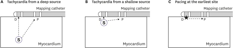
Figure 1 Mapping catheter position during tachycardia (A, B) and pacing at the earliest site for depth estimation (C). Stars indicate pacing site.D = distal electrode; P = proximal electrode; S = focal activation source.
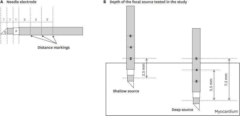
Figure 2 Needle electrode and mapping catheter. (A) Structure of the needle electrode. (B) Depth of focal source simulation tested in the present study.D = distal electrode; P = proximal electrode.
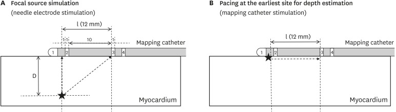
Figure 3 Mapping catheter position during focal source simulation (A) and pacing at the earliest site for depth estimation (B). Stars indicate stimulation sites.D = distal electrode; l = inter-electrode distance.
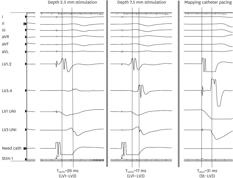
Figure 4 Representative electrograms during focal source simulation (depth 2.5 mm and 7.5 mm) and mapping catheter pacing at the earliest site. I, II, III, aVR, aVL, and aVF are ECG channels. LV1, 2 and LV3, 4 are bipolar electrograms. LV1 UNI and LV3 UNI are unipolar electrograms.aVF = augmented vector foot; aVL = augmented vector left; aVR = augmented vector right; ECG = electrocardiogram; LV = left ventricular; Need cath = needle electrode catheter; Tpace = time interval between distal and proximal electrodes during distal electrode pacing of the mapping catheter; Ttachy = time interval between distal and proximal electrodes of the mapping catheter during needle electrode pacing.
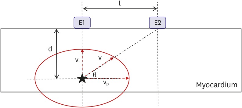
Figure 5 Experimental setting assumptions. Star indicates focal activation source.d = depth; E1 and E2 = electrodes; l = inter-electrode distance; θ = vector angle of v; v = average conduction velocity from the source to the proximal electrode (E2); vp = average parallel conduction velocity; vt = average transmural conduction velocity.
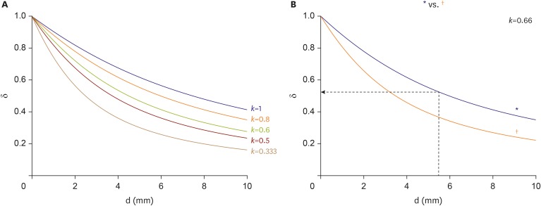
Figure 6 δ versus d of the focal source. (A) δ depending on different conditions of anisotropic conduction (k=vt/vp). (B) δ according to inter-electrode distance of the mapping catheter when k=0.66.δ = depth index; d = depth; vp = average parallel conduction velocity; vt = average transmural conduction velocity.*2-10-2 spacing; †2-5-2 spacing.
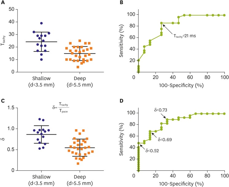
Figure 7 Ttachy in shallow source and deep source simulation (A) and ROC analysis results (B). δ in shallow source and deep source simulation (C) and ROC results (D). Bars in (A) and (C) indicate mean±standard deviation.δ = depth index; d = depth; ROC = receiver operating characteristic; Tpace = time interval between distal and proximal electrodes during distal electrode pacing of the mapping catheter; Ttachy = time interval between distal and proximal electrodes of the mapping catheter during needle electrode pacing.
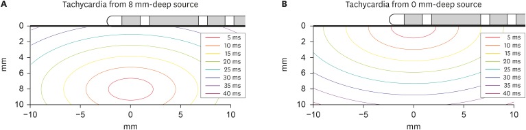
Figure 8 Isochronal map based on present study results for deep source (A) and shallow source (B) simulation when vp=0.45 mm/ms and vt=0.29 mm/ms.vp = average parallel conduction velocity; vt = average transmural conduction velocity.
Reference
-
1. Dorwarth U, Fiek M, Remp T, et al. Radiofrequency catheter ablation: different cooled and noncooled electrode systems induce specific lesion geometries and adverse effects profiles. Pacing Clin Electrophysiol. 2003; 26:1438–1445. PMID: 12914619.2. Nath S, DiMarco JP, Haines DE. Basic aspects of radiofrequency catheter ablation. J Cardiovasc Electrophysiol. 1994; 5:863–876. PMID: 7874332.3. Nakagawa H, Yamanashi WS, Pitha JV, et al. Comparison of in vivo tissue temperature profile and lesion geometry for radiofrequency ablation with a saline-irrigated electrode versus temperature control in a canine thigh muscle preparation. Circulation. 1995; 91:2264–2273. PMID: 7697856.4. Nakagawa H, Jackman WM. The role of contact force in atrial fibrillation ablation. J Atr Fibrillation. 2014; 7:1027. PMID: 27957075.5. Clerc L. Directional differences of impulse spread in trabecular muscle from mammalian heart. J Physiol. 1976; 255:335–346. PMID: 1255523.
- Full Text Links
-
- Actions
-
Cited
- CITED
-
- Close
- Share
-
- Similar articles
-
- Editorial: Simple Maneuver for Estimating the Depth of the Focal Activation Source in Myocardium
- The Effect of the Valsalva Maneuver on the External Jugular Vein
- Incidental Detection of Ischemic Myocardium on 68 Ga-FAPI PET/CT
- Effect of light source and shade on depth of cure of composites
- The Usefulness of Dobutamine Stress Echocardiography for Evaluation of Viable Myocardium in Hibernating Myocardium
