Metallic Artifacts on MR Imaging and Methods for Their Reduction
- Affiliations
-
- 1Department of Radiology, Inje University Busan Paik Hospital, Busan, Korea. hyejungchoo@gmail.com
- 2Department of Radiology, Research Institute of Radiological Science and Center for Clinical Imaging Data Science (CCIDS), Yonsei University College of Medicine, Seoul, Korea.
- KMID: 2469181
- DOI: http://doi.org/10.3348/jksr.2020.81.1.41
Abstract
- Metallic artifacts on MR imaging are typically induced by differences in magnetic susceptibility between the metallic implant and surrounding tissue. Conventional techniques for metal artifact reduction require MR machines with low field strength, shift in the frequency-encoding and phase-encoding directions according to the axis of metallic implant, increased receiver bandwidth and matrix, decreased slice thickness, and utilization of the short tau inversion recovery or Dixon method for fat-suppression. Slice-encoding for metal artifact correction and multi-acquisition variable-resonance image combination can dramatically reduce the number of metallic artifacts. However, these sequences have a considerably long acquisition time. Furthermore, the recently developed acceleration techniques including compressed sensing can solve this problem.
MeSH Terms
Figure
-
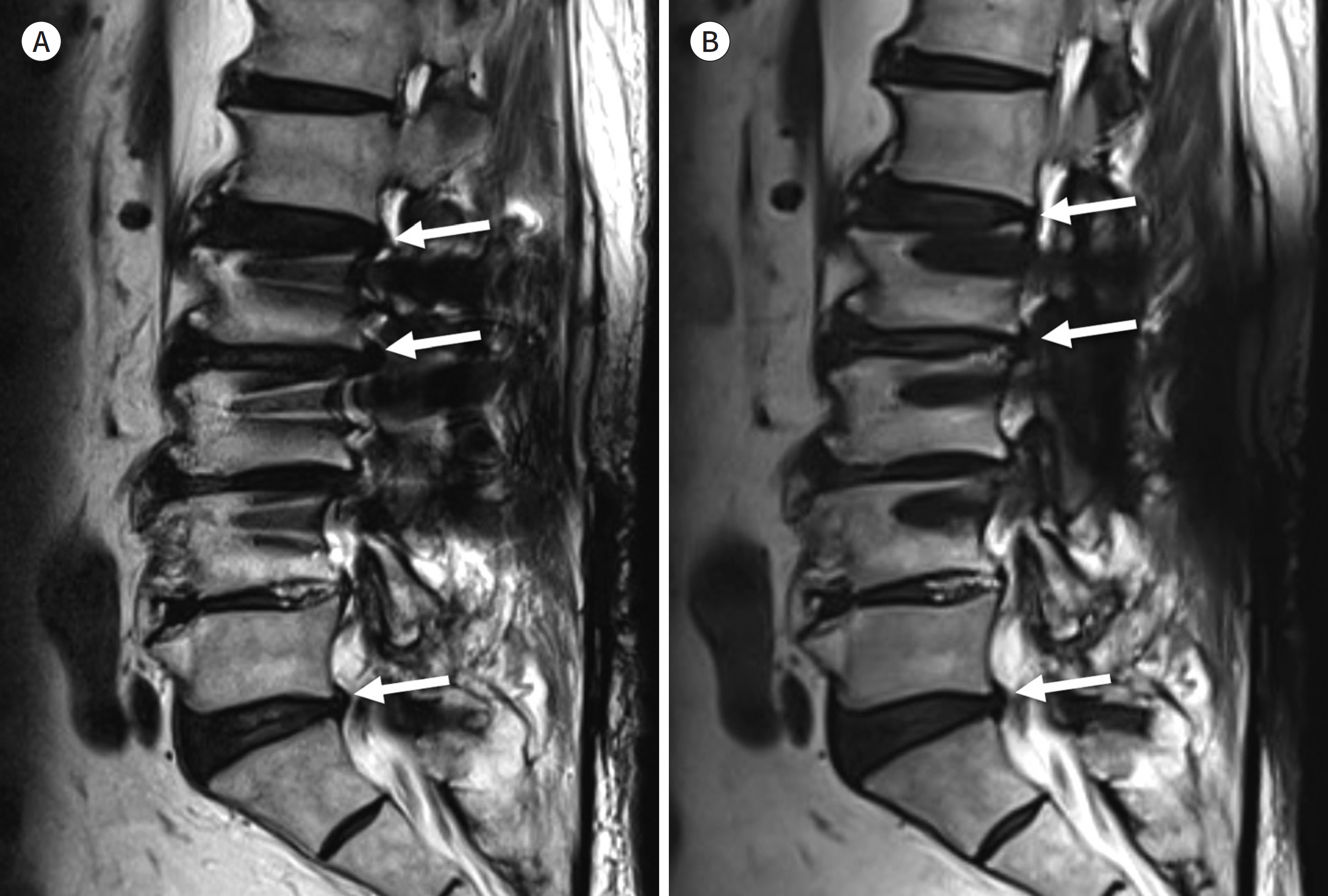
Fig. 1. 74-year-old man with posterior fusion of L2-3-4. A, B. Sagittal T2-weighted image shows the signal void and pile-up next to the screws (A). The out-pouching of the intervertebral discs (arrows) can be identified on this image (A). However, it may be a pseudo-lesion associated with a geographic distortion considering the fact that the out-pouching of the intervertebral disc (arrows) is less prominent on the slice encoding for metal artifact correction combined with T2-weighted image (B).
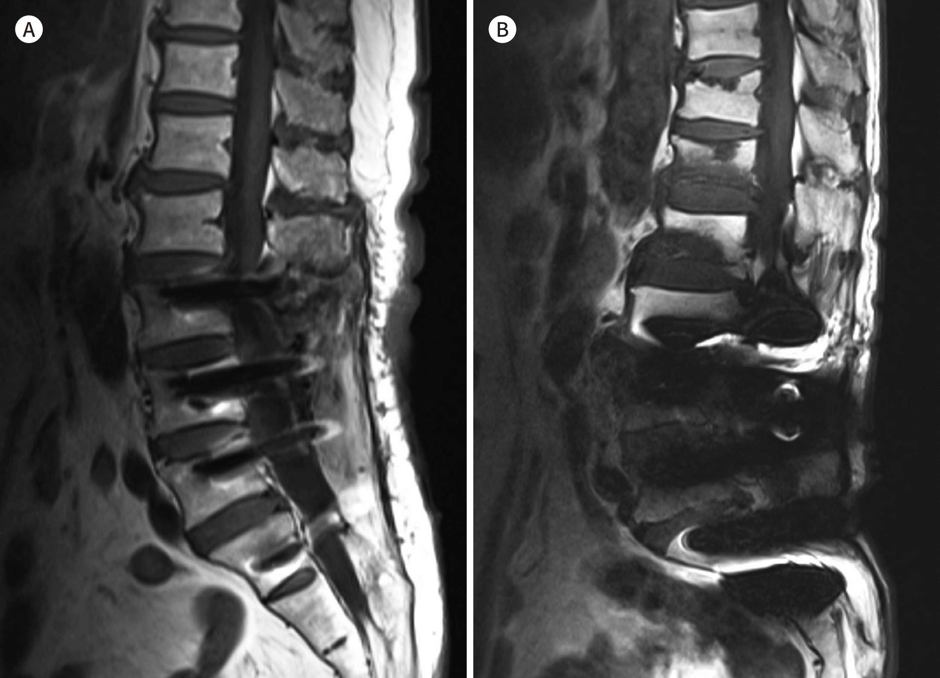
Fig. 2. Types of metallic materials. A, B. T1-weighted images with spinal fusion using titanium in 59-year-old man (A) and using stainless steel in 63-year-old man (B). There are more metal artifacts in (B) than in (A).
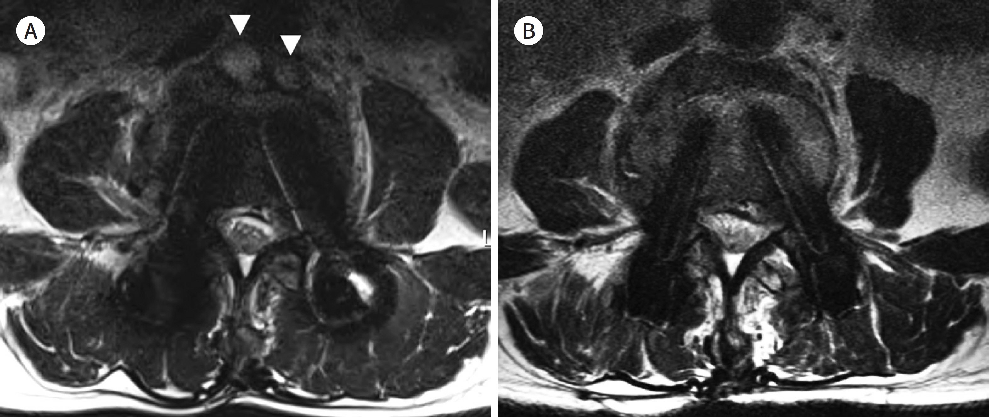
Fig. 3. 63-year-old man with postoperative spinal infection. A, B. Axial T2-weighted image (TR/TE = 2000/100, receiver bandwidth = 230 Hz/pixel) obtained by a 3 T MR machine shows the prevertebral abscesses (arrowheads) (A). The followup MRI outcome after a 3-month antibiotic therapy has been imaged by a 1.5 T machine (B). The image (TR/TE = 3550/123, receiver bandwidth = 163 Hz/pixel) shows resolution of prevertebral abscesses. The metal artifact of the screws (B) is smaller than that in the initial MRI with 3 T (A). TE = echo time, TR = repetition time

Fig. 4. Effect of receiver bandwidth. Each voxel is encoded by a wider frequency range in a high receiver bandwidth than in a low bandwidth. Therefore, the local frequency errors generated by metal implant do not significantly influence the spatial encoding in a high receiver bandwidth. BW = bandwidth, Gr = readout gradient axis, Gs = slice selection gradient axis Modified from Khodarahmi et al. Semin Musculoskelet Radiol 2019; 23:e68-e81, with permission of Thieme (10)
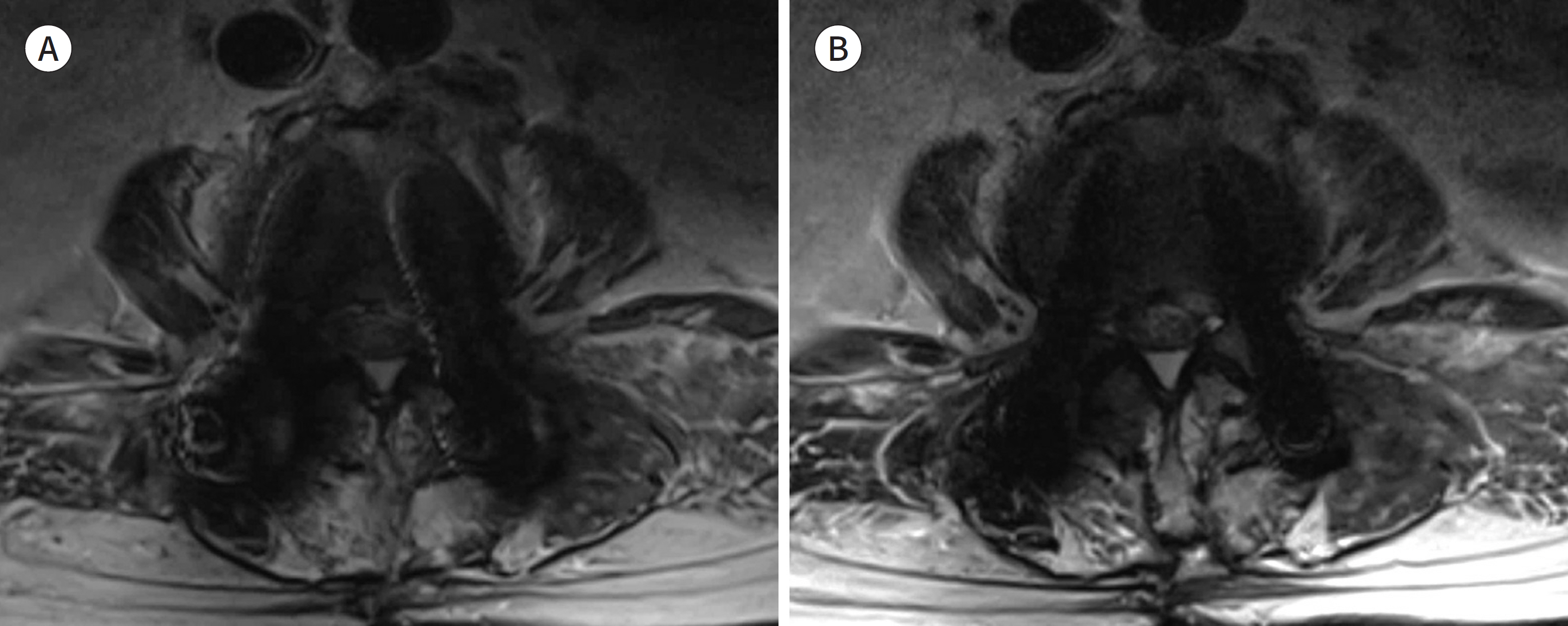
Fig. 5. 66-year-old woman with posterior fusion of L3-4-5. A, B. The receiver bandwidths for the two axial T2-weighted images are 150 Hz/pixel (A) and 550 Hz/pixel (B), and the other parameters for (A) and (B) are the same. The metal artifact size for the bilateral screws is considerably larger in (A) than in (B).

Fig. 6. 59-year-old man with septic arthritis at left hip joint. A. Simple radiography shows the presence of antibiotic beads, spacer, and metallic device at the left hip joint and femur. Right hip joint and right femur are deformed. B. The frequency-selective fat suppressed T2 weighted image applied with SEMAC shows incomplete fat suppression around the metallic implant. C. The water-only image from Dixon technique shows more homogenous fat suppression than that in (B). However, it shows zebra artifact or Moire fringes (arrowheads) around the metallic instrument. D. Although the short tau inversion recovery with SEMAC shows more homogenous fat suppression than that in (B) and (C), its signal-to-noise ratio is relatively poor. E, F. Compared with T1 weighted image with SEMAC after contrast administration (E), subtraction image (F) between pre-contrast and post-contrast T1 weighted images with SEMAC shows obvious contrast-enhancement around the left hip joint (arrowheads) and right acetabulum (arrow). SEMAC = slice-encoding for metal artifact correction
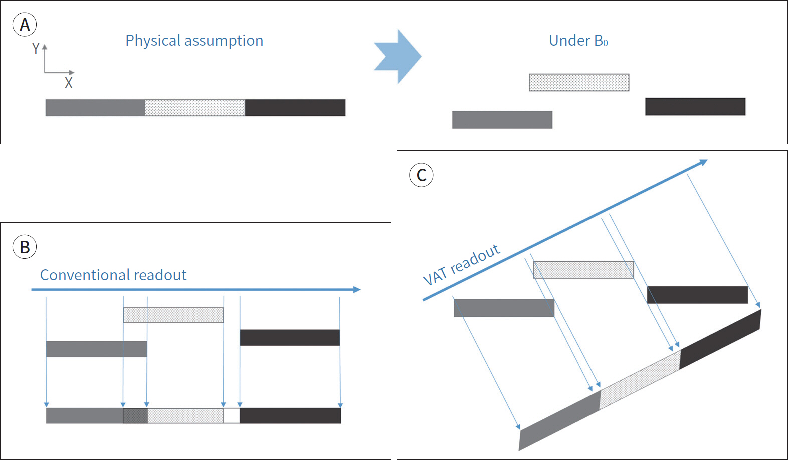
Fig. 7. Concepts of VAT. A, B. Three materials with different magnetic susceptibility are assumed to be aligned in a row (A). The materials are displaced under the magnetic field and demonstrate signal overlap and signal void (A and B). C. VAT by applying the gradient in slice selection direction during the readout results in tilting the angle of the readout direction and resolves the in-plane artifacts. However, the image blurring can be seen at the margins of the materials. VAT = view angle tilting Modified from Khodarahmi et al. Semin Musculoskelet Radiol 2019;23:e68-e81, with permission of Thieme (10)
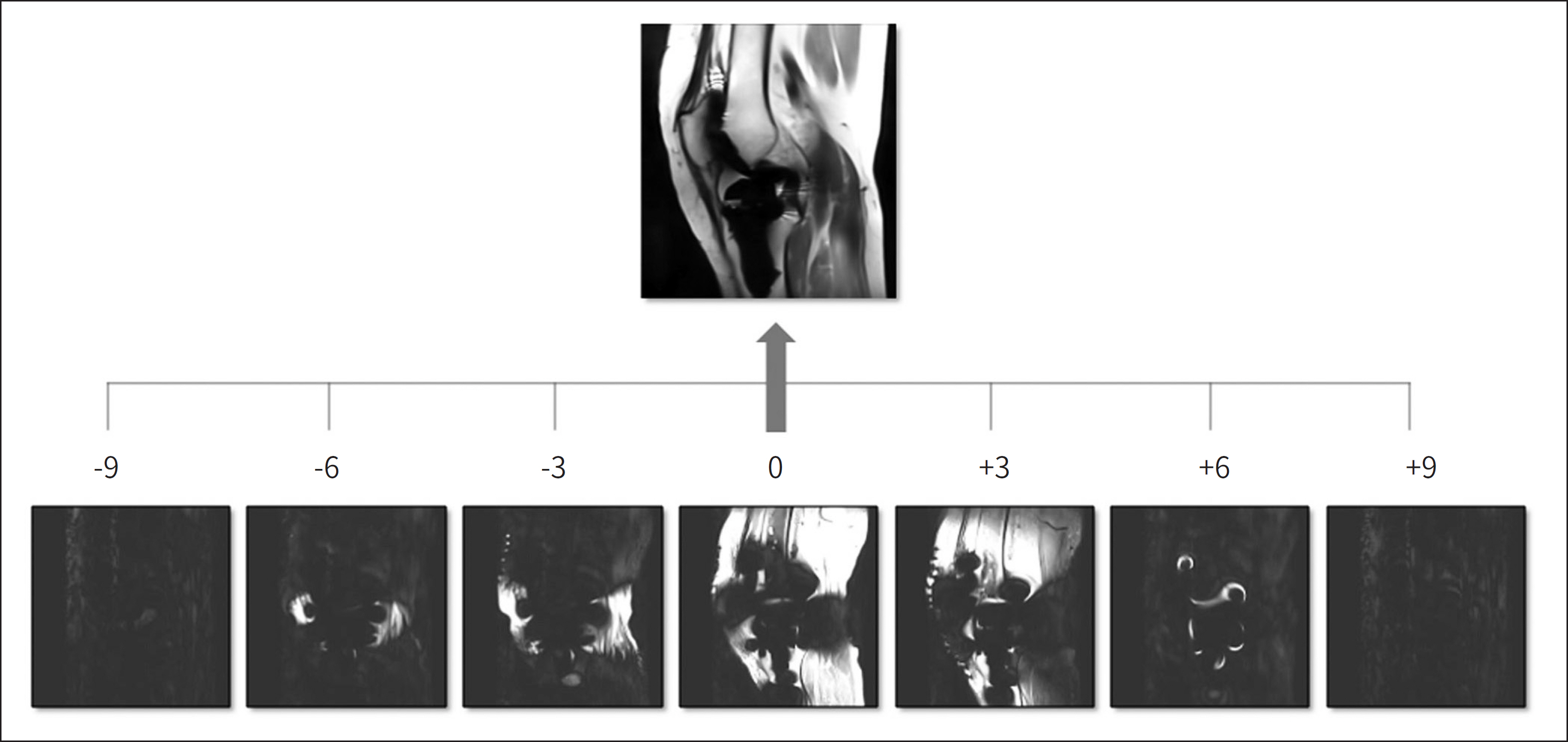
Fig. 8. SEMAC with SEMAC factor of 19. Individual encoding step images are obtained by additional phase-encoding steps in a slice-selection direc-tion. The combination of these partitions makes a final SEMAC image. SEMAC = slice encoding for metal artifact correction

Fig. 9. 39-year-old man with ACL, PLC, and medial collateral ligament repair. A. Simple radiography shows the several staples and anchor for ACL and PLC reconstruction. B. Conventional T2-weighted image shows the signal void and signal pile-up around the metallic devices inserted at the lateral femoral condyle. C. SEMAC T2-weighted image shows a metal artifact, which is smaller than that in (A), at the lateral femoral condyle. The typical ripple artifact around the metallic implants is present on the SEMAC image (arrowheads). ACL = anterior cruciate reconstruction, PLC = posterolateral corner reconstruction, SEMAC = slice-encoding for metal artifact correction
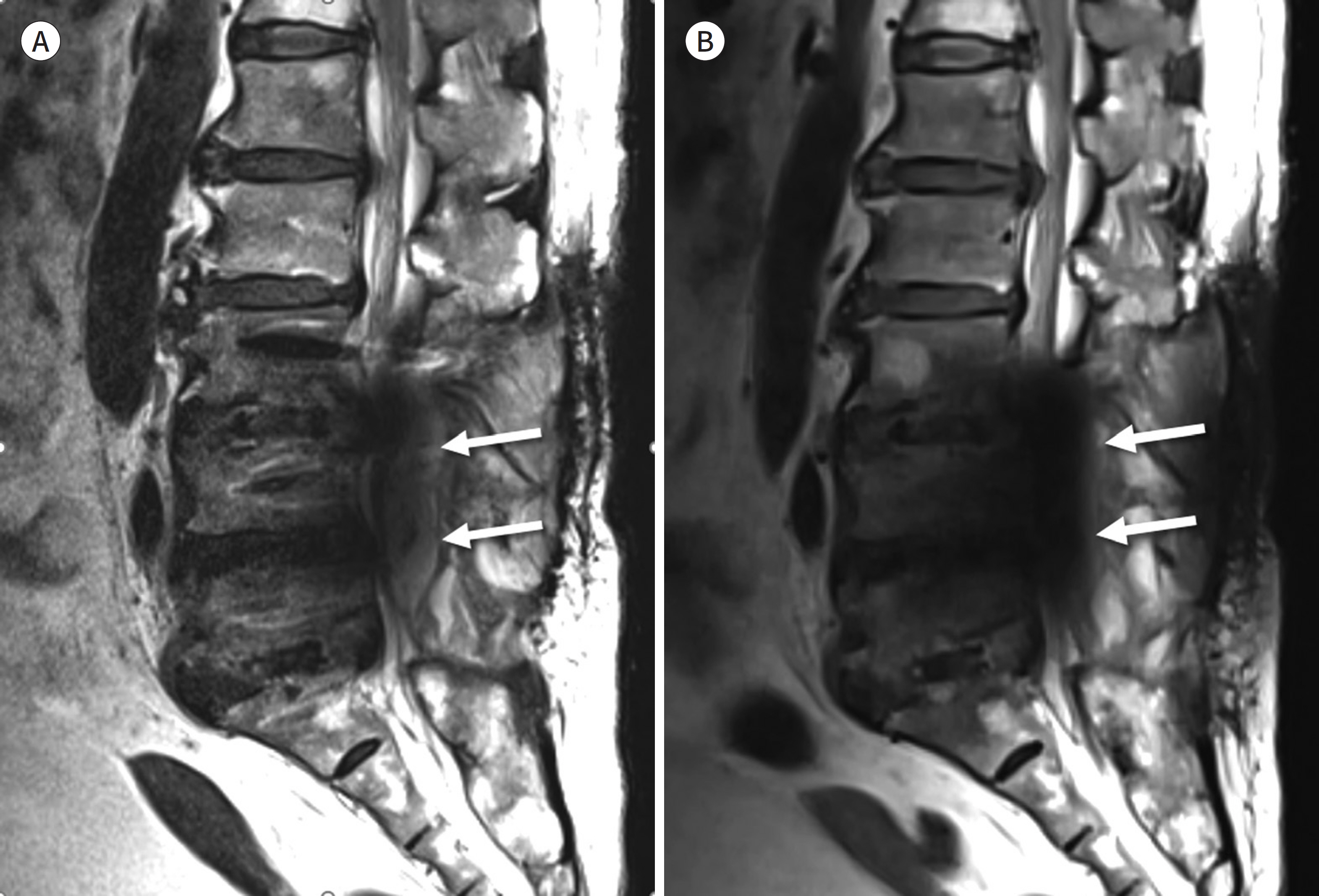
Fig. 10. 75-year-old woman with posterior fusion of L3-4-5 and interbody fusion of L3-4, L4-5, and L5-S1. A, B. Sagittal T2-weighted image with high receiver bandwidth (545 Hz/pixel) shows fluid collection (arrows) at the posterior epidural space of L4-5 (A). However, this fluid collection is obscured by the signal void (arrows) at the spinal central canal on slice-encoding for metal artifact correction T2-weighted image (B).

Fig. 11. 55-year-old man with acetabular fixation. A, B. Compared with conventional coronal proton density-weighted image (A), the artifact size of the metallic instruments is small in MAVRIC-SL (B). However, MAVRIC-SL demonstrates image blurring. MAVRIC-SL = multi-acquisition variable-resonance image combination-selective
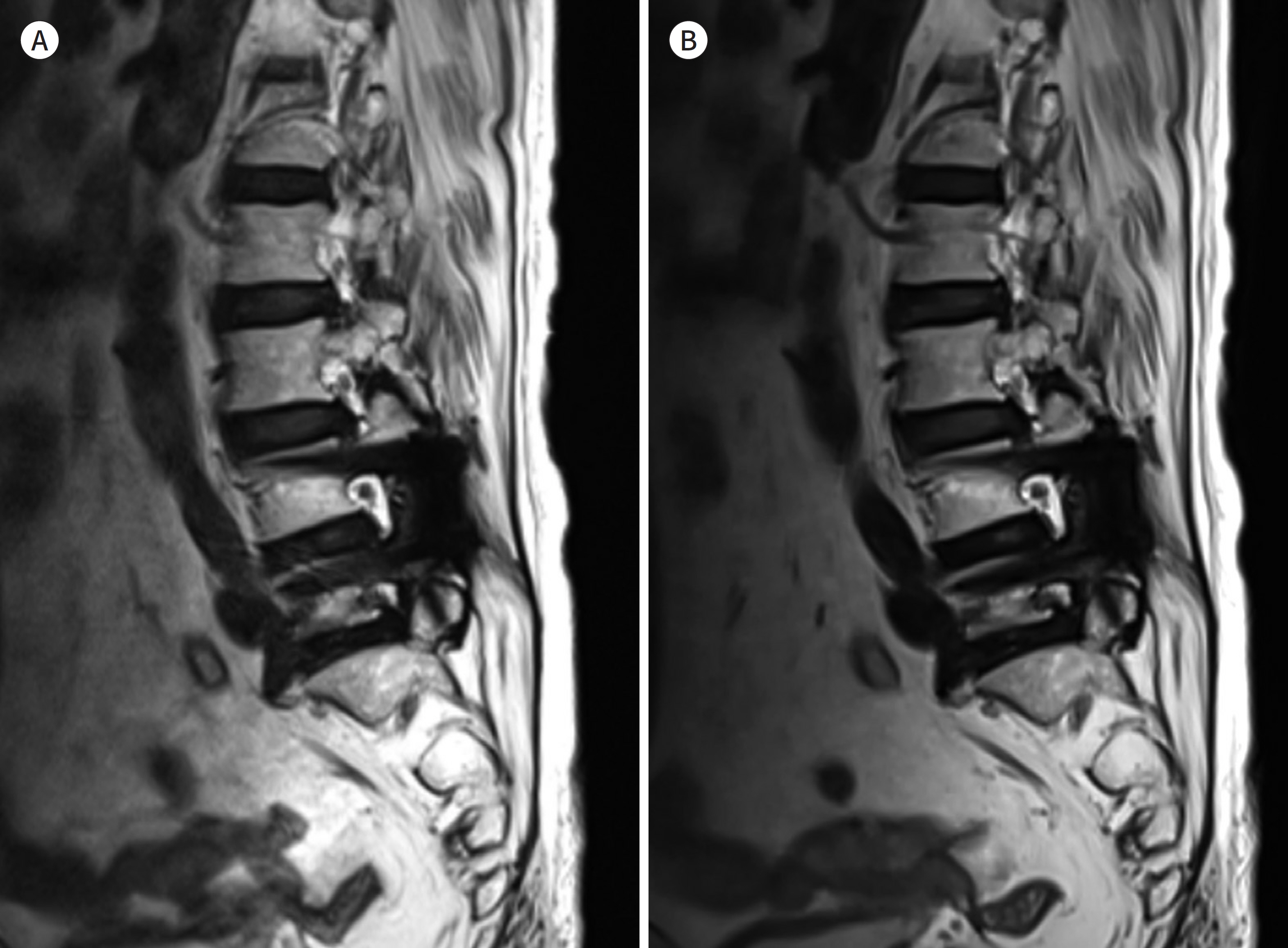
Fig. 12. 75-year-old woman with posterior fusion of L4-5. A, B. T2-weighted images with SEMAC (A) and T2-weighted images with compressed-sensing SEMAC (B) show similar image quality. The acquisition times for compressed-sensing SEMAC (B) is particularly shorter than that for SEMAC (A) and are quite different: 6 minutes 35 seconds for T2-weighted images with SEMAC and 3 minutes 10 seconds for compressed-sensing SEMAC. SEMAC = slice-encoding for metal artifact correction
Reference
-
1. Thiele K, Perka C, Matziolis G, Mayr HO, Sostheim M, Hube R. Current failure mechanisms after knee arthroplasty have changed: polyethylene wear is less common in revision surgery. J Bone Joint Surg Am. 2015; 97:715–720.
Article2. Rajaee SS, Campbell JC, Mirocha J, Paiement GD. Increasing burden of total hip arthroplasty revisions in patients between 45 and 64 years of age.J Bone Joint Surg Am. 2018; 100:449–458.3. Talbot BS, Weinberg EP. MR imaging with metal-suppression sequences for evaluation of total joint arthroplasty.Radiographics. 2015; 36:209–225.4. Schenck JF. The role of magnetic susceptibility in magnetic resonance imaging: MRI magnetic compatibility of the first and second kinds.Med Phys. 1996; 23:815–850.5. Koch KM, Hargreaves BA, Pauly KB, Chen W, Gold GE, King KF. Magnetic resonance imaging near metal implants.J Magn Reson Imaging. 2010; 32:773–787.6. Jungmann PM, Agten CA, Pfirrmann CW, Sutter R. Advances in MRI around metal.J Magn Reson Imaging. 2017; 46:972–991.7. Ariyanayagam T, Malcolm PN, Toms AP. Advances in metal artifact reduction techniques for periprosthetic soft tissue imaging.Semin Musculoskelet Radiol. 2015; 19:328–334.8. Dillenseger J, Moliere S, Choquet P, Goetz C, Ehlinger M, Bierry G. An illustrative review to understand and manage metal-induced artifacts in musculoskeletal MRI: a primer and updates.Skeletal Radiol. 2016; 45:677–688.9. Eustace S, Jara H, Goldberg R, Fenlon H, Mason M, Melhem ER, et al. A comparison of conventional spin-echo and turbo spin-echo imaging of soft tissues adjacent to orthopedic hardware.AJR Am J Roentgenol. 1998; 170:455–458.10. Khodarahmi I, Isaac A, Fishman EK, Dalili D, Fritz J. Metal about the hip and artifact reduction techniques: from basic concepts to advanced imaging.Semin Musculoskelet Radiol. 2019; 23:e68–e81.11. Zou YF, Chu B, Wang CB, Hu ZY. Evaluation of MR issues for the latest standard brands of orthopedic metal implants: plates and screws. Eur J Radiol. 2015; 84:450–457.
Article12. Koff MF, Shah P, Koch KM, Potter HG. Quantifying image distortion of orthopedic materials in magnetic resonance imaging.J Magn Reson Imaging. 2013; 38:610–618.13. Lee MJ, Kim S, Lee SA, Song HT, Huh YM, Kim DH, et al. Overcoming artifacts from metallic orthopedic implants at high-field-strength MR imaging and multidetector CT.Radiographics. 2007; 27:791–803.14. Aboelmagd SM, Malcolm PN, Toms AP. Magnetic resonance imaging of metal artifact reduction sequences in the assessment of metal-on-metal hip prostheses.Reports Med Imaging. 2014; 7:65–74.15. Feng DX, McCauley JP, Morgan-Curtis FK, Salam RA, Pennell DR, Loveless ME, et al. Evaluation of 39 medical implants at 7.0 T.Br J Radiol. 2015; 88:20150633.16. Vandevenne JE, Vanhoenacker FM, Parizel PM, Butts Pauly K, Lang RK. Reduction of metal artefacts in musculoskeletal MR imaging.JBR-BTR. 2007; 90:345–349.17. Chang EY, Bae WC, Chung CB. Imaging the knee in the setting of metal hardware.Magn Reson Imaging Clin N Am. 2014; 22:765–786.18. Kumar NM, De Cesar Netto C, Schon LC, Fritz J. Metal artifact reduction magnetic resonance imaging around arthroplasty implants: the negative effect of long echo trains on the implant-related artifact.Invest Radiol. 2017; 52:310–316.19. Hargreaves BA, Worters PW, Pauly KB, Pauly JM, Koch KM, Gold GE. Metal-induced artifacts in MRI.AJR Am J Roentgenol. 2011; 197:547–555.20. Bachschmidt TJ, Sutter R, Jakob PM, Pfirrmann CW, Nittka M. Knee implant imaging at 3 Tesla using high-bandwidth radiofrequency pulses.J Magn Reson Imaging. 2015; 41:1570–1580.21. Buckwalter KA. Optimizing imaging techniques in the postoperative patient.Semin Musculoskelet Radiol. 2007; 11:261–272.22. Ulbrich EJ, Sutter R, Aguiar RF, Nittka M, Pfirrmann CW. STIR sequence with increased receiver bandwidth of the inversion pulse for reduction of metallic artifacts. AJR Am J Roentgenol. 2012; 199:W735–W742.
Article23. Cha JG, Jin W, Lee MH, Kim DH, Park JS, Shin WH, et al. Reducing metallic artifacts in postoperative spinal imaging: usefulness of IDEAL contrast-enhanced T1- and T2-weighted MR imaging–phantom and clinical studies. Radiology. 2011; 259:885–893.
Article24. Cha JG, Hong HS, Park JS, Paik SH, Lee HK. Practical application of iterative decomposition of water and fat with echo asymmetry and least-squares estimation (IDEAL) imaging in minimizing metallic artifacts.Korean J Radiol. 2012; 13:332–341.25. Müller GM, Månsson S, Müller MF, Von Schewelov T, Nittka M, Ekberg O, et al. MR imaging with metal artifact-reducing sequences and gadolinium contrast agent in a case-control study of periprosthetic abnormalities in patients with metal-on-metal hip prostheses. Skeletal Radiol. 2014; 43:1101–1112.
Article26. Khodarahmi I, Nittka M, Fritz J. Leaps in technology: advanced MR imaging after total hip arthroplasty.Semin Musculoskelet Radiol. 2017; 21:604–615.27. Cho ZH, Kim DJ, Kim YK. Total inhomogeneity correction including chemical shifts and susceptibility by view angle tilting. Med Phys. 1988; 15:7–11.
Article28. Butts K, Pauly JM, Gold GE. Reduction of blurring in view angle tilting MRI.Magn Reson Med. 2005; 53:418–424.29. Chen CA, Chen W, Goodman SB, Hargreaves BA, Koch KM, Lu W, et al. New MR imaging methods for metallic implants in the knee: artifact correction and clinical impact.J Magn Reson Imaging. 2011; 33:1121–1127.30. Deligianni X, Bieri O, Elke R, Wischer T, Egelhof T. Optimization of scan time in MRI for total hip prostheses: SEMAC tailoring for prosthetic implants containing different types of metals.Rofo. 2015; 187:1116–1122.31. Filli L, Jud L, Luechinger R, Nanz D, Andreisek G, Runge VM, et al. Material-dependent implant artifact reduction using SEMAC-VAT and MAVRIC: a prospective MRI phantom study.Invest Radiol. 2017; 52:381–387.32. Den Harder JC, Van Yperen GH, Blume UA, Bos C. Ripple artifact reduction using slice overlap in slice encoding for metal artifact correction. Magn Reson Med. 2015; 73:318–324.
Article33. Park C, Lee E, Yeo Y, Kang Y, Lee JW, Ahn JM, et al. Spine MR images in patients with pedicle screw fixation: comparison of conventional and SEMAC-VAT sequences at 1.5 T.Magn Reson Imaging. 2018; 54:63–70.34. Hayter CL, Koff MF, Shah P, Koch KM, Miller TT, Potter HG. MRI after arthroplasty: comparison of MAVRIC and conventional fast spin-echo techniques. AJR Am J Roentgenol. 2011; 197:W405–W411.
Article35. Choi SJ, Koch KM, Hargreaves BA, Stevens KJ, Gold GE. Metal artifact reduction with MAVRIC SL at 3-T MRI in patients with hip arthroplasty. AJR Am J Roentgenol. 2015; 204:140–147.
Article36. Koch KM, Brau AC, Chen W, Gold GE, Hargreaves BA, Koff M, et al. Imaging near metal with a MAVRIC-SEMAC hybrid.Magn Reson Med. 2011; 65:71–82.37. Liebl H, Heilmeier U, Lee S, Nardo L, Patsch J, Schuppert C, et al. In vitro assessment of knee MRI in the presence of metal implants comparing MAVRIC-SL and conventional fast spin echo sequences at 1.5 and 3 T field strength.J Magn Reson Imaging. 2015; 41:1291–1299.38. Ai T, Padua A, Goerner F, Nittka M, Gugala Z, Jadhav S, et al. SEMAC-VAT and MSVAT-SPACE sequence strate-gies for metal artifact reduction in 1.5T magnetic resonance imaging.Invest Radiol. 2012; 47:267–276.39. Den Harder JC, Van Yperen GH, Blume UA, Bos C. Off-resonance suppression for multispectral MR imaging near metallic implants.Magn Reson Med. 2015; 73:233–243.40. Hargreaves BA, Chen W, Lu W, Alley MT, Gold GE, Brau AC, et al. Accelerated slice encoding for metal artifact correction.J Magn Reson Imaging. 2010; 31:987–996.41. Lustig M, Donoho D, Pauly JM. Sparse MRI: the application of compressed sensing for rapid MR imaging. Magn Reson Med. 2007; 58:1182–1195.
Article42. Fritz J, Ahlawat S, Demehri S, Thawait GK, Raithel E, Gilson WD, et al. Compressed sensing SEMAC: 8-fold ac-celerated high resolution metal artifact reduction MRI of cobalt-chromium knee arthroplasty implants.Invest Radiol. 2016; 51:666–676.43. Fritz J, Fritz B, Thawait GK, Raithel E, Gilson WD, Nittka M, et al. Advanced metal artifact reduction MRI of metal-on-metal hip resurfacing arthroplasty implants: compressed sensing acceleration enables the time-neutral use of SEMAC.Skeletal Radiol. 2016; 45:1345–1356.44. De Cesar Netto C, Fonseca LF, Fritz B, Stern SE, Raithel E, Nittka M, et al. Metal artifact reduction MRI of total ankle arthroplasty implants. Eur Radiol. 2018; 28:2216–2227.
Article
- Full Text Links
-
- Actions
-
Cited
- CITED
-
- Close
- Share
-
- Similar articles
-
- MR imaging of metallic artifacts
- Practical Application of Iterative Decomposition of Water and Fat with Echo Asymmetry and Least-Squares Estimation (IDEAL) Imaging in Minimizing Metallic Artifacts
- A study of artifacts in MR imaging induced by metalic aneurysm clips
- Determining the Location of Metallic Needle from MR Images Distorted by Susceptibility Difference
- Artifacts by dental materials on magnetic resonance imaging
