Geometrical design characteristics of orthodontic mini-implants predicting maximum insertion torque
- Affiliations
-
- 1Department of Pediatric Dentistry and Orthodontics, School of Medicine, University of Rijeka, Rijeka, Croatia. visnja.katic@gmail.com
- 2Department of Mechanical Engineering Design, Faculty of Engineering, University of Rijeka, Rijeka, Croatia.
- KMID: 2273274
- DOI: http://doi.org/10.4041/kjod.2014.44.4.177
Abstract
OBJECTIVE
To determine the unique contribution of geometrical design characteristics of orthodontic mini-implants on maximum insertion torque while controlling for the influence of cortical bone thickness.
METHODS
Total number of 100 cylindrical orthodontic mini-implants was used. Geometrical design characteristics of ten specimens of ten types of cylindrical self-drilling orthodontic mini-implants (Ortho Easy(R), Aarhus, and Dual Top(TM)) with diameters ranging from 1.4 to 2.0 mm and lengths of 6 and 8 mm were measured. Maximum insertion torque was recorded during manual insertion of mini-implants into bone samples. Cortical bone thickness was measured. Retrieved data were analyzed in a multiple regression model.
RESULTS
Significant predictors for higher maximum insertion torque included larger outer diameter of implant, higher lead angle of thread, and thicker cortical bone, and their unique contribution to maximum insertion torque was 12.3%, 10.7%, and 24.7%, respectively.
CONCLUSIONS
The maximum insertion torque values are best controlled by choosing an implant diameter and lead angle according to the assessed thickness of cortical bone.
Keyword
MeSH Terms
Figure
-

Figure 1 Orthodontic mini-implant with handheld screwdriver.
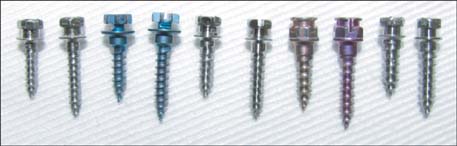
Figure 2 Tested mini-implants (from left to right): Dual Top™ (Jeil Medical Corp., Seoul, Korea) 1.4 × 6 mm, and 1.4 × 8 mm; Aarhus (MEDICON eG, Tuttlingen, Germany) 1.5 × 6 mm, and 1.5 × 8 mm; Dual Top™ 1.6 × 6 mm, and 1.6 × 8 mm; Ortho Easy® (FORESTADENT®, Pforzheim, Germany) 1.7 × 6 mm, and 1.7 × 8 mm; Dual Top™ 2.0 × 6 mm, and 2.0 × 8 mm.
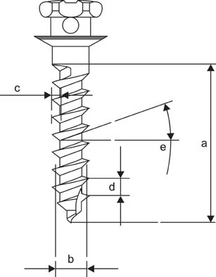
Figure 3 Geometrical design characteristics of mini-implants (length [a], outer diameter [b], depth [c], pitch [d], and lead angle [e] of the thread).
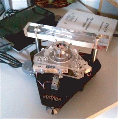
Figure 4 Torque-measuring device with mounted bone sample.
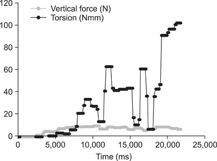
Figure 5 Representative curve for manual insertion of orthodontic mini-implants.
Cited by 1 articles
-
Stress distributions in peri-miniscrew areas from cylindrical and tapered miniscrews inserted at different angles
Sung-Hwan Choi, Seong-Jin Kim, Kee-Joon Lee, Sang-Jin Sung, Youn-Sic Chun, Chung-Ju Hwang
Korean J Orthod. 2016;46(4):189-198. doi: 10.4041/kjod.2016.46.4.189.
Reference
-
1. Kanomi R. Mini-implant for orthodontic anchorage. J Clin Orthod. 1997; 31:763–767.2. Motoyoshi M. Clinical indices for orthodontic mini-implants. J Oral Sci. 2011; 53:407–412.
Article3. Tseng YC, Hsieh CH, Chen CH, Shen YS, Huang IY, Chen CM. The application of mini-implants for orthodontic anchorage. Int J Oral Maxillofac Surg. 2006; 35:704–707.
Article4. Poggio PM, Incorvati C, Velo S, Carano A. "Safe zones": a guide for miniscrew positioning in the maxillary and mandibular arch. Angle Orthod. 2006; 76:191–197.5. Cheng SJ, Tseng IY, Lee JJ, Kok SH. A prospective study of the risk factors associated with failure of mini-implants used for orthodontic anchorage. Int J Oral Maxillofac Implants. 2004; 19:100–106.6. Meredith N. Assessment of implant stability as a prognostic determinant. Int J Prosthodont. 1998; 11:491–501.7. Motoyoshi M, Hirabayashi M, Uemura M, Shimizu N. Recommended placement torque when tightening an orthodontic mini-implant. Clin Oral Implants Res. 2006; 17:109–114.
Article8. Pithon MM, Nojima MG, Nojima LI. In vitro evaluation of insertion and removal torques of orthodontic mini-implants. Int J Oral Maxillofac Surg. 2011; 40:80–85.
Article9. Wilmes B, Drescher D. Impact of bone quality, implant type, and implantation site preparation on insertion torques of mini-implants used for orthodontic anchorage. Int J Oral Maxillofac Surg. 2011; 40:697–703.
Article10. Lim SA, Cha JY, Hwang CJ. Insertion torque of orthodontic miniscrews according to changes in shape, diameter and length. Angle Orthod. 2008; 78:234–240.
Article11. Xu Z, Zhao L, Wu Y, Wei X, Wang J, Tang N, et al. Histomorphometric and biomechanical analyses of the osseointegration of loaded orthodontic microscrews inserted at different cortical bone thickness sites. Oral Surg Oral Med Oral Pathol Oral Radiol. 2012; doi: 10.1016/j.oooo.2012.06.007[Epub ahead of print].
Article12. Pithon MM, Nojima MG, Nojima LI. Primary stability of orthodontic mini-implants inserted into maxilla and mandible of swine. Oral Surg Oral Med Oral Pathol Oral Radiol. 2012; 113:748–754.
Article13. Studenmund AH, Cassidy HJ. Instructor's manual to accompany. Using econometrics, a practical guide. Boston: Little Brown;1987.14. Miyawaki S, Koyama I, Inoue M, Mishima K, Sugahara T, Takano-Yamamoto T. Factors associated with the stability of titanium screws placed in the posterior region for orthodontic anchorage. Am J Orthod Dentofacial Orthop. 2003; 124:373–378.
Article15. American Gear Manufacturers Association, American National Standards Institute. Gear nomenclature, definitions of terms with symbols: AGMA standard. Alexandria: American Gear Manufacturers Association;2005.16. Dalstra M, Cattaneo PM, Melsen B. Load transfer of miniscrews for orthodontic anchorage. Orthodontics. 2004; 1:53–62.17. Wilmes B, Panayotidis A, Drescher D. Fracture resistance of orthodontic mini-implants: a biomechanical in vitro study. Eur J Orthod. 2011; 33:396–401.
Article18. Kondo S, Okada Y, Iseki H, Hori T, Takakura K, Kobayashi A, et al. Thermological study of drilling bone tissue with a high-speed drill. Neurosurgery. 2000; 46:1162–1168.
Article19. Brisman DL. The effect of speed, pressure, and time on bone temperature during the drilling of implant sites. Int J Oral Maxillofac Implants. 1996; 11:35–37.20. Toews AR, Bailey JV, Townsend HG, Barber SM. Effect of feed rate and drill speed on temperatures in equine cortical bone. Am J Vet Res. 1999; 60:942–944.21. Kim JS, Choi SH, Cha SK, Kim JH, Lee HJ, Yeom SS, et al. Comparison of success rates of orthodontic mini-screws by the insertion method. Korean J Orthod. 2012; 42:242–248.
Article22. Cha JY, Yu HS, Hwang CJ. The validation of Periotest values for the evaluation of orthodontic mini-implants' stability. Korean J Orthod. 2010; 40:167–175.
Article23. Aparicio C, Lang NP, Rangert B. Validity and clinical significance of biomechanical testing of implant/bone interface. Clin Oral Implants Res. 2006; 17:Suppl 2. 2–7.
Article24. Kim SJ, Yoo J, Kim YS, Shin SW. Temperature change in pig rib bone during implant site preparation by low-speed drilling. J Appl Oral Sci. 2010; 18:522–527.
Article25. Marković A, Mišić T, Miličić B, Calvo-Guirado JL, Aleksić Z, Ðinić A. Heat generation during implant placement in low-density bone: effect of surgical technique, insertion torque and implant macro design. Clin Oral Implants Res. 2013; 24:798–805.
Article26. Friberg B, Sennerby L, Roos J, Johansson P, Strid CG, Lekholm U. Evaluation of bone density using cutting resistance measurements and microradiography: an in vitro study in pig ribs. Clin Oral Implants Res. 1995; 6:164–171.
Article
- Full Text Links
-
- Actions
-
Cited
- CITED
-
- Close
- Share
-
- Similar articles
-
- Effect of cutting flute length and shape on insertion and removal torque of orthodontic mini-implants
- Effect of dual pitch mini-implant design and diameter of an orthodontic mini-implant on the insertion and removal torque
- Insertion and removal torques according to orthodontic mini-screw design
- Influence of surface treatment on the insertion pattern of self-drilling orthodontic mini-implants
- Mechanical analysis of the taper shape and length of orthodontic mini-implant for initial stability
