Principle and Comprehension of Ultrasound Imaging
- Affiliations
-
- 1Department of Orthopedic Surgery, Ewha Womans University School of Medicine, Seoul, Korea. sjshin622@ewha.ac.kr
- KMID: 1494144
- DOI: http://doi.org/10.4055/jkoa.2013.48.5.325
Abstract
- Ultrasound is a sound wave beyond the audible frequency. Owing to technological development, the extent of use of ultrasound in orthopaedics is expanding. Ultrasound is produced by a piezoelectric effect and matter is requires for propagation. According to the characteristics of matter, the velocity of propagation differs and the images are the overall result of the interaction of reflection, refraction, absorption, scattering, transmission, and attenuation. The most important device is the transducer, which differs according to the array of piezoelectric elements and shapes the way it used and where it is used. Mode B is currently the most common image and many images which help to make diagnosis easier, such as doppler flow imaging, extended field of view imaging, compound imaging and three-dimensional imaging, are under developments. Ultrasound produces variable artifacts and during interpretation of ultrasound images, artifacts could interfere with correct diagnosis. In order to avoid creation of artifacts, profound knowledge of each artifact is needed. Therefore, precise understanding and interpretation of the ultrasound image is essential for proper diagnosis and use of ultrasound.
MeSH Terms
Figure
-
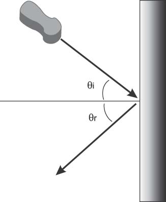
Figure 1 Reflection. When an ultrasound wave is directed at a right angle to the interface, the wave is reflected toward the sound source. These interfaces are called specular reflectors, and the angle of reflection (θr) of a sound wave is equal to the angle of incidence (θi).
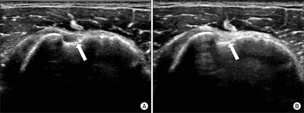
Figure 2 Transverse scan of the long head of the biceps tendon. Echogenicity at perpendicular scan to biceps tendon (A: arrow) is different from that of non-perpendicular scan (B: arrow).
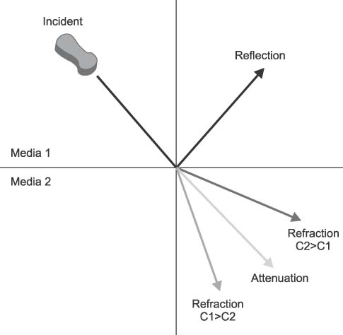
Figure 3 Refraction. When an ultrasound wave strikes at the interface between two media at an angle other than 90°, the transmitted wave is refracted. When the velocity of an ultrasound wave in media 1 is greater than that in media 2 (C1>C2), the angle of reflection is decreased, and when velocity of an ultrasound wave in the media 1 is less than in media 2 (C1
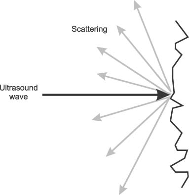
Figure 4 Scattering. When the ultrasound wave encounters an irregular interface, it scatters in many directions.
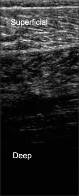
Figure 5 Attenuation. The display shows a gradual loss of the intensity of a signal as it passes from superficial to deep tissue.
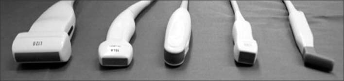
Figure 6 Various types of ultrasound transducers.
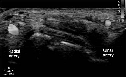
Figure 7 Doppler image obtained from the wrist (radial artery and ulnar artery). Courtesy of Philips Healthcare.
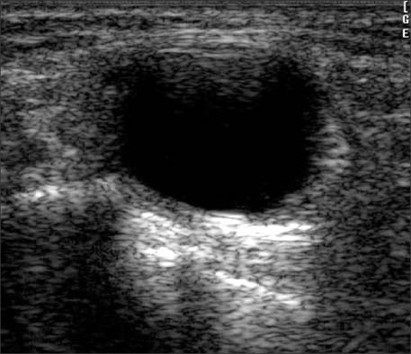
Figure 8 Posterior acoustic enhancement. Abnormal echogenicity is seen as a result of the fluid-filled cyst.
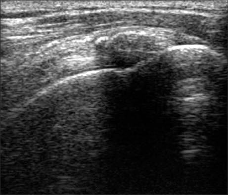
Figure 9 Acoustic shadowing. Long axis scan of calcific tendinitis shows acoustic shadowing posterior to echogenic calcific deposits.
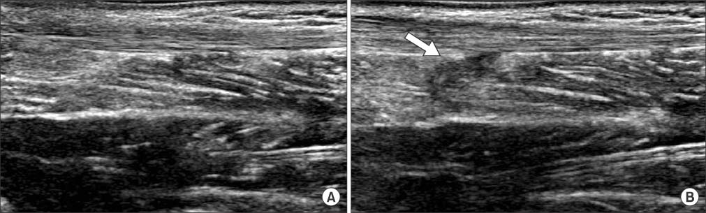
Figure 10 Anisotropy. Long axis scan of the Achilles tendon. (A) Normal hyperechoic tendon. (B) When the transducer is angled along the longitudinal axis of the tendon, causing hypoechogenicity (arrow) from anisotropy.
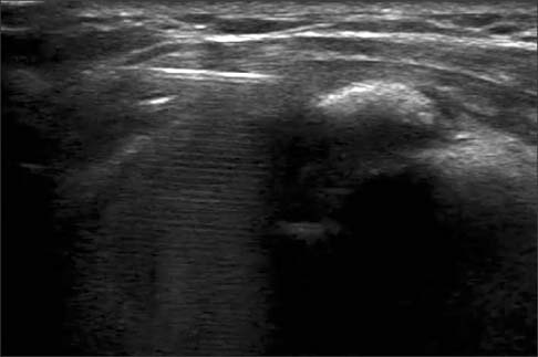
Figure 11 Reverberation. The display shows ultrasound echoes being repeatedly reflected when a needle is inserted into subacromial space.
Reference
-
1. Wells PN. Ultrasound imaging. Phys Med Biol. 2006; 51:R83–R98.
Article2. Bianchi S, Martinoli C. Ultrasound of the musculoskeletal system. Berlin, New York: Springer;2007.3. Bushberg JT, Seibert JA, Leidholdt EM, Boone JM. The essential physics of medical imaging. Philadelphia: Lippincott Williams & Wilkins;2002. p. 469–553.4. Claudon M, Tranquart F, Evans DH, Lefèvre F, Correas M. Advances in ultrasound. Eur Radiol. 2002; 12:7–18.
Article5. Carpenter DA. Ultrasonic transducers. Clin Diagn Ultrasound. 1980; 5:31.6. Hangiandreou NJ. AAPM/RSNA physics tutorial for residents. Topics in US: B-mode US: basic concepts and new technology. Radiographics. 2003; 23:1019–1033.7. Whittingham TA. Medical diagnostic applications and sources. Prog Biophys Mol Biol. 2007; 93:84–110.
Article8. Lin EC, Middleton WD, Teefey SA. Extended field of view sonography in musculoskeletal imaging. J Ultrasound Med. 1999; 18:147–152.
Article9. Entrekin RR, Porter BA, Sillesen HH, Wong AD, Cooperberg PL, Fix CH. Real-time spatial compound imaging: application to breast, vascular, and musculoskeletal ultrasound. Semin Ultrasound CT MR. 2001; 22:50–64.
Article10. Hünerbein M, Raschke M, Khodadadyan C, Hohenberger P, Haas NP, Schlag PM. Three-dimensional ultrasonography of bone and soft tissue lesions. Eur J Ultrasound. 2001; 13:17–23.
Article11. Feldman MK, Katyal S, Blackwood MS. US artifacts. Radiographics. 2009; 29:1179–1189.
Article
- Full Text Links
-
- Actions
-
Cited
- CITED
-
- Close
- Share
-
- Similar articles
-
- Ultrasound-based Liver Elastography: Recent Advances
- Functional Magnetic Resonance Imaging of the Brain: Principle and Practical Application
- Ultrasound of the Gallbladder
- Elastography of the Thyroid Glands
- A Technical Note on a Novel Technique for the Evaluation of Breast Excision Specimen: Automated Breast Ultrasound System
