Optimization of exposure parameters and relationship between subjective and technical image quality in cone-beam computed tomography
- Affiliations
-
- 1Department of Oral and Maxillofacial Radiology, School of Dentistry, Chonbuk National University, Jeonju, Korea. kkj1512@jbnu.ac.kr
- KMID: 2450180
- DOI: http://doi.org/10.5624/isd.2019.49.2.139
Abstract
- PURPOSE
This study was performed to investigate the effect of exposure parameters on image quality obtained using a cone-beam computed tomography (CBCT) scanner and the relationship between physical factors and clinical image quality depending on the diagnostic task.
MATERIALS AND METHODS
CBCT images of a SedentexCT IQ phantom and a real skull phantom were obtained under different combinations of tube voltage and tube current (Alphard 3030 CBCT scanner, 78-90 kVp and 2-8 mA). The images obtained using a SedentexCT IQ phantom were analyzed technically, and the physical factors of image noise, contrast resolution, spatial resolution, and metal artifacts were measured. The images obtained using a real skull phantom were evaluated for each diagnostic task by 6 oral and maxillofacial radiologists, and each setting was classified as acceptable or unacceptable based on those evaluations. A statistical analysis of the relationships of exposure parameters and physical factors with observer scores was conducted.
RESULTS
For periapical diagnosis and implant planning, the tube current of the acceptable images was significantly higher than that of the unacceptable images. Image noise, the contrast-to-noise ratio (CNR), the line pair chart on the Z axis, and modulation transfer function (MTF) values showed statistically significant differences between the acceptable and unacceptable image groups. The cut-off values obtained using receiver operating characteristic curves for CNR and MTF 10 were useful for determining acceptability.
CONCLUSION
Tube current had a major influence on clinical image quality. CNR and MTF 10 were useful physical factors that showed significantly associations with clinical image quality.
Figure
-
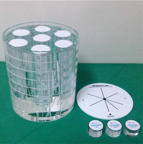
Fig. 1 A head-sized cylindrical polymethyl methacrylate phantom.
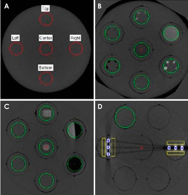
Fig. 2 Cone-beam computed tomographic axial images obtained using a SedentexCT IQ phantom show the regions of interest calculated by the Radia software. A. Image noise section. B. Contrast resolution section. C. Spatial resolution section. D. Artifact section.
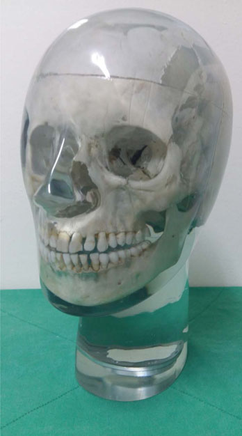
Fig. 3 A real skull phantom with a soft-tissue replica.
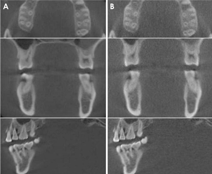
Fig. 4 Cone-beam computed tomographic images show examples of acceptable (A) and the unacceptable (B) image quality.
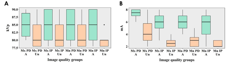
Fig. 5 Differences between acceptable and unacceptable images in tube voltage (A) and current (B). A: acceptable group, Un: unacceptable group, PD: periapical diagnosis, IP: implant planning, Mx: maxilla, Mn: mandible.
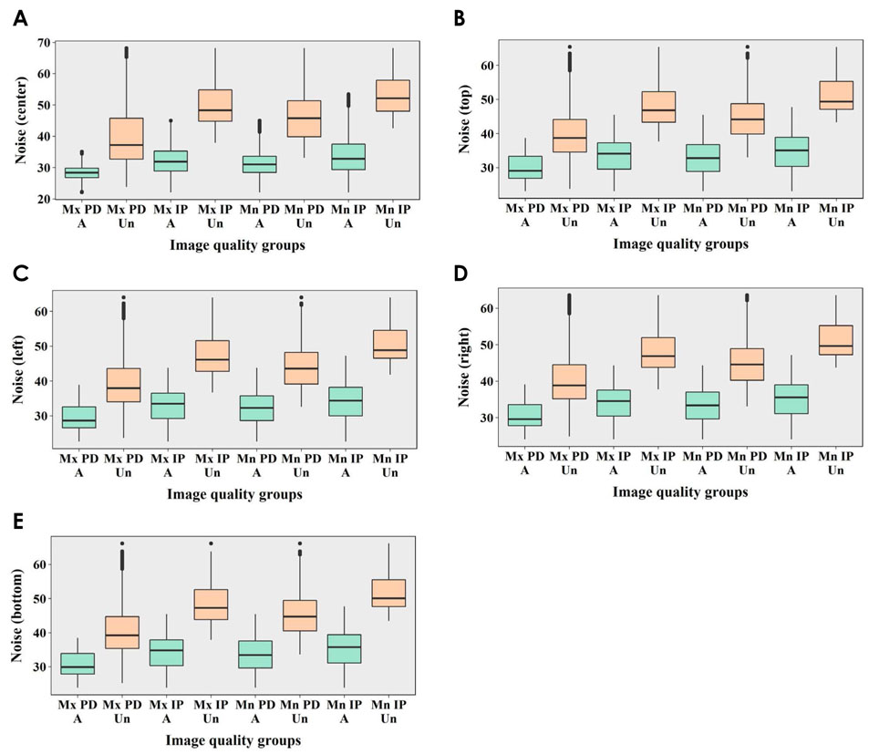
Fig. 6 Differences between acceptable and unacceptable images in image noise values according to the measurement positions. A: Acceptable group, Un: unacceptable group, PD: periapical diagnosis, IP: implant planning, Mx: maxilla, Mn: mandible.
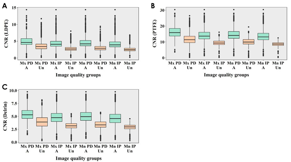
Fig. 7 Differences between acceptable and unacceptable images in the contrast-to-noise ratio (CNR) according to the rod type. LDPE: low-density polyethylene, PTFE: polytetrafluoroethylene, A: acceptable group, Un: unacceptable group, PD: periapical diagnosis, IP: implant planning, Mx: maxilla, Mn: mandible.
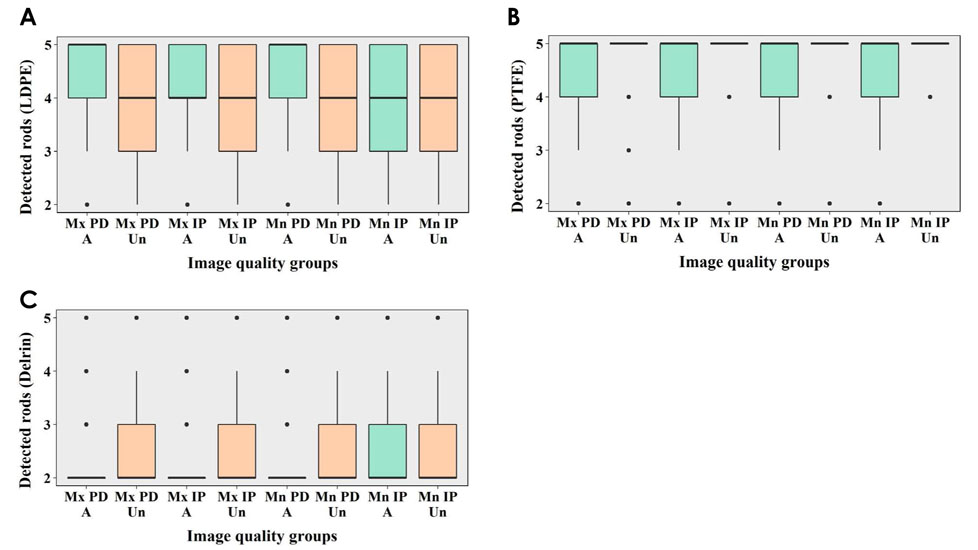
Fig. 8 Differences between acceptable and unacceptable images in the number of detected rods according to the rod type. LDPE: low-density polyethylene, PTFE: polytetrafluoroethylene, A: acceptable group, Un: unacceptable group, PD: periapical diagnosis, IP: implant planning, Mx: maxilla, Mn: mandible.
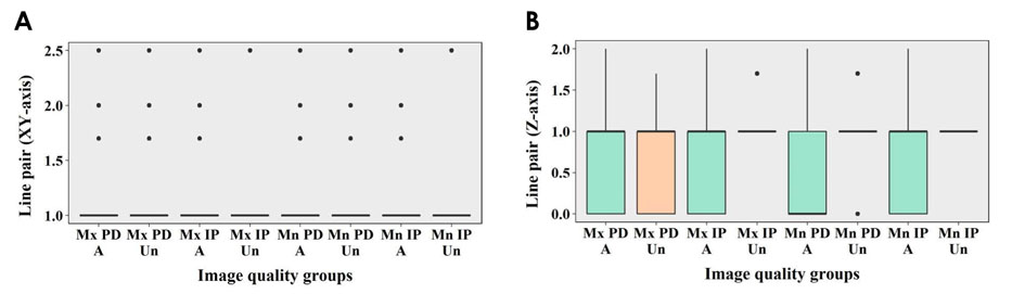
Fig. 9 Differences between acceptable and unacceptable images in the results of line pair charts according to the axes. A: acceptable group, Un: unacceptable group, PD: periapical diagnosis, IP: implant planning, Mx: maxilla, Mn: mandible.

Fig. 10 Differences between acceptable and unacceptable images in the modulation transfer function (MTF) values. A: acceptable group, Un: unacceptable group, PD: periapical diagnosis, IP: implant planning, Mx: maxilla, Mn: mandible.
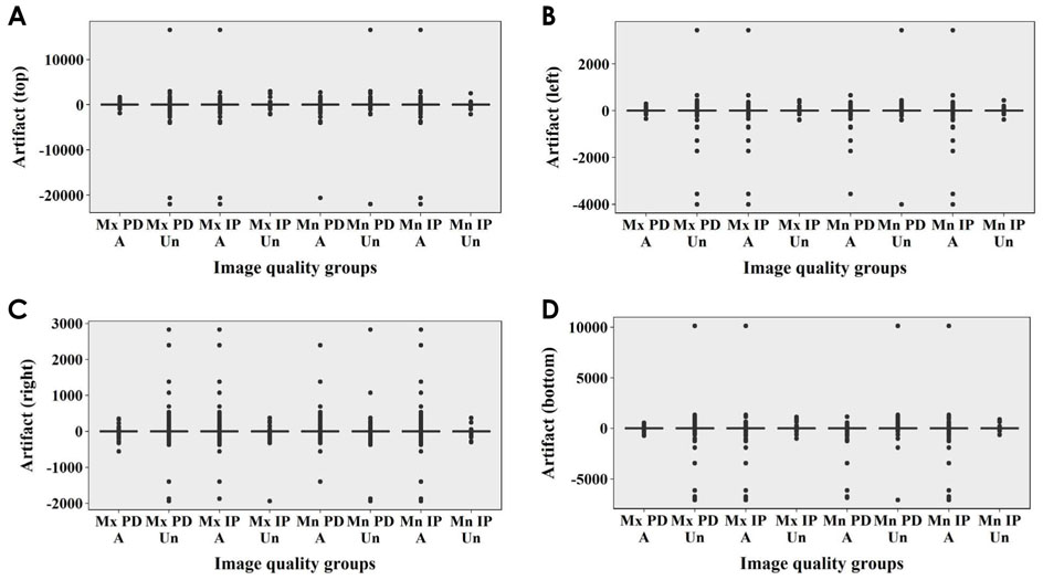
Fig. 11 Differences between acceptable and unacceptable images in the results of metal artifact tests according to the measurement positions. A: acceptable group, Un: unacceptable group, PD: periapical diagnosis, IP: implant planning, Mx: maxilla, Mn: mandible.
Reference
-
1. Bamba J, Araki K, Endo A, Okano T. Image quality assessment of three cone beam CT machines using the SEDENTEXCT CT phantom. Dentomaxillofac Radiol. 2013; 42:20120445.
Article2. Scarfe WC, Farman AG, Sukovic P. Clinical applications of cone-beam computed tomography in dental practice. J Can Dent Assoc. 2006; 72:75–80.3. Ludlow JB, Davies-Ludlow LE, White SC. Patient risk related to common dental radiographic examinations: the impact of 2007 International Commission on Radiological Protection recommendations regarding dose calculation. J Am Dent Assoc. 2008; 139:1237–1243.4. Al-Okshi A, Theodorakou C, Lindh C. Dose optimization for assessment of periodontal structures in cone beam CT examinations. Dentomaxillofac Radiol. 2017; 46:20160311.
Article5. Cohnen M, Kemper J, Möbes O, Pawelzik J, Mödder U. Radiation dose in dental radiology. Eur Radiol. 2002; 12:634–637.
Article6. Ludlow JB, Davies-Ludlow LE, Brooks SL, Howerton WB. Dosimetry of 3 CBCT devices for oral and maxillofacial radiology: CB Mercuray, NewTom 3G and i-CAT. Dentomaxillofac Radiol. 2006; 35:219–226.
Article7. Choi JW, Lee SS, Choi SC, Heo MS, Huh KH, Yi WJ, et al. Relationship between physical factors and subjective image quality of cone-beam computed tomography images according to diagnostic task. Oral Surg Oral Med Oral Pathol Oral Radiol. 2015; 119:357–365.
Article8. Pauwels R, Seynaeve L, Henriques JC, de Oliveira-Santos C, Souza PC, Westphalen FH, et al. Optimization of dental CBCT exposures through mAs reduction. Dentomaxillofac Radiol. 2015; 44:20150108.
Article9. Liang X, Jacobs R, Hassan B, Li L, Pauwels R, Corpas L, et al. A comparative evaluation of cone beam computed tomography (CBCT) and multi-slice CT (MSCT) Part I. On subjective image quality. Eur J Radiol. 2010; 75:265–269.10. Ludlow JB, Walker C. Assessment of phantom dosimetry and image quality of i-CAT FLX cone-beam computed tomography. Am J Orthod Dentofacial Orthop. 2013; 144:802–817.
Article11. Loubele M, Jacobs R, Maes F, Denis K, White S, Coudyzer W, et al. Image quality vs radiation dose of four cone beam computed tomography scanners. Dentomaxillofac Radiol. 2008; 37:309–318.12. Suomalainen A, Kiljunen T, Käser Y, Peltola J, Kortesniemi M. Dosimetry and image quality of four dental cone beam computed tomography scanners compared with multislice computed tomography scanners. Dentomaxillofac Radiol. 2009; 38:367–378.
Article13. Loubele M, Van Assche N, Carpentier K, Maes F, Jacobs R, van Steenberghe D, et al. Comparative localized linear accuracy of small-field cone-beam CT and multislice CT for alveolar bone measurements. Oral Surg Oral Med Oral Pathol Oral Radiol Endod. 2008; 105:512–518.
Article14. Loubele M, Maes F, Schutyser F, Marchal G, Jacobs R, Suetens P. Assessment of bone segmentation quality of cone-beam CT versus multislice spiral CT: a pilot study. Oral Surg Oral Med Oral Pathol Oral Radiol Endod. 2006; 102:225–234.
Article15. Pauwels R, Beinsberger J, Stamatakis H, Tsiklakis K, Walker A, Bosmans H, et al. Comparison of spatial and contrast resolution for cone-beam computed tomography scanners. Oral Surg Oral Med Oral Pathol Oral Radiol. 2012; 114:127–135.
Article16. Pauwels R, Stamatakis H, Manousaridis G, Walker A, Michielsen K, Bosmans H, et al. Development and applicability of a quality control phantom for dental cone-beam CT. J Appl Clin Med Phys. 2011; 12:3478.
Article17. International Commission on Radiological Protection. Managing patient dose in digital radiology. A report of the International Commission on Radiological Protection. Ann ICRP. 2004; 34:1–73.18. Bushberg JT, Seibert JA, Leidholdt EM Jr, Boone JM. The essential physics of medical imaging. 3rd ed. Philadelphia: Lippincott Williams & Wilkins;2012. p. 60–99.19. Brüllmann D, Schulze RK. Spatial resolution in CBCT machines for dental/maxillofacial applications - what do we know today? Dentomaxillofac Radiol. 2015; 44:20140204.20. Freitas DQ, Fontenele RC, Nascimento EHL, Vasconcelos TV, Noujeim M. Influence of acquisition parameters on the magnitude of cone beam computed tomography artifacts. Dentomaxillofac Radiol. 2018; 47:20180151.
Article21. Landis JR, Koch GG. The measurement of observer agreement for categorical data. Biometrics. 1977; 33:159–174.
Article22. Pauwels R, Silkosessak O, Jacobs R, Bogaerts R, Bosmans H, Panmekiate S. A pragmatic approach to determine the optimal kVp in cone beam CT: balancing contrast-to-noise ratio and radiation dose. Dentomaxillofac Radiol. 2014; 43:20140059.
Article23. Hidalgo Rivas JA, Horner K, Thiruvenkatachari B, Davies J, Theodorakou C. Development of a low-dose protocol for cone beam CT examinations of the anterior maxilla in children. Br J Radiol. 2015; 88:20150559.
Article24. Kwong JC, Palomo JM, Landers MA, Figueroa A, Hans MG. Image quality produced by different cone-beam computed tomography settings. Am J Orthod Dentofacial Orthop. 2008; 133:317–327.
Article25. Sur J, Seki K, Koizumi H, Nakajima K, Okano T. Effects of tube current on cone-beam computerized tomography image quality for presurgical implant planning in vitro. Oral Surg Oral Med Oral Pathol Oral Radiol Endod. 2010; 110:e29–e33.
Article26. Dawood A, Brown J, Sauret-Jackson V, Purkayastha S. Optimization of cone beam CT exposure for pre-surgical evaluation of the implant site. Dentomaxillofac Radiol. 2012; 41:70–74.
Article27. Panmekiate S, Apinhasmit W, Petersson A. Effect of electric potential and current on mandibular linear measurements in cone beam CT. Dentomaxillofac Radiol. 2012; 41:578–582.
Article28. McGuigan MB, Duncan HF, Horner K. An analysis of effective dose optimization and its impact on image quality and diagnostic efficacy relating to dental cone beam computed tomography (CBCT). Swiss Dent J. 2018; 128:297–316.29. Goulston R, Davies J, Horner K, Murphy F. Dose optimization by altering the operating potential and tube current exposure time product in dental cone beam CT: a systematic review. Dentomaxillofac Radiol. 2016; 45:20150254.
Article30. de Oliveira MV, Wenzel A, Campos PS, Spin-Neto R. Quality assurance phantoms for cone beam computed tomography: a systematic literature review. Dentomaxillofac Radiol. 2017; 46:20160329.
Article31. Choi JW. Analysis of the priority of anatomic structures according to the diagnostic task in cone-beam computed tomographic images. Imaging Sci Dent. 2016; 46:245–249.
Article32. Watanabe H, Nomura Y, Kuribayashi A, Kurabayashi T. Spatial resolution measurements by Radia diagnostic software with SEDENTEXCT image quality phantom in cone beam CT for dental use. Dentomaxillofac Radiol. 2018; 47:20170307.
Article33. Watanabe H, Honda E, Tetsumura A, Kurabayashi T. A comparative study for spatial resolution and subjective image characteristics of a multi-slice CT and a cone-beam CT for dental use. Eur J Radiol. 2011; 77:397–402.
Article34. Pauwels R, Stamatakis H, Bosmans H, Bogaerts R, Jacobs R, Horner K, et al. Quantification of metal artifacts on cone beam computed tomography images. Clin Oral Implants Res. 2013; 24:Suppl A100. 94–99.
Article35. Schulze RK, Berndt D, d'Hoedt B. On cone-beam computed tomography artifacts induced by titanium implants. Clin Oral Implants Res. 2010; 21:100–107.
Article
- Full Text Links
-
- Actions
-
Cited
- CITED
-
- Close
- Share
-
- Similar articles
-
- Analysis of the priority of anatomic structures according to the diagnostic task in cone-beam computed tomographic images
- Correlation analysis between radiation exposure and the image quality of cone-beam computed tomography in the dental clinical environment
- Three-dimensional imaging modalities in endodontics
- Linear accuracy of cone-beam computed tomography and a 3-dimensional facial scanning system: An anthropomorphic phantom study
- Cone beam computed tomography and intraoral radiography for diagnosis of dental abnormalities in dogs and cats
