Improvement of a 4-Channel Spiral-Loop RF Coil Array for TMJ MR Imaging at 7T
- Affiliations
-
- 1Neuroscience Research Institute, Gachon University, Incheon, Republic of Korea. zcho@gachon.ac.kr
- KMID: 2099844
- DOI: http://doi.org/10.13104/jksmrm.2012.16.2.103
Abstract
- PURPOSE
In an attempt to further improve the radiofrequency (RF) magnetic (B1) field strength in temporomandibular joint (TMJ) imaging, a 4-channel spiral-loop coil array with RF circuitry was designed and compared with a 4-channel single-loop coil array in terms of B1 field, RF transmit (B1+), signal-to-noise ratio (SNR), and applicability to TMJ imaging in 7T MRI.
MATERIALS AND METHODS
The single- and 4-channel spiral-loop coil arrays were constructed based on the electromagnetic (EM) simulation for the investigation of B1 field. To evaluate the computer simulation results, the B1 field and B1 + maps were measured in 7T.
RESULTS
In the EM simulation result and MRI study at 7T, the 4-channel spiral-loop coil array found a superior B1 performance and a higher B1 + profile inside the human head as well as a slightly better SNR than the 4-channel single-loop coil array.
CONCLUSION
Although B1 fields are produced under the influence of the dielectric properties of the subject rather than the coil configuration alone at 7T, each RF coil exhibited not only special but also specific characteristics that could make it suited for specific application such as TMJ imaging.
Keyword
MeSH Terms
Figure
-

Fig. 1 Geometry of (a) single-channel single-loop coil and (b) single-channel spiral-loop coil, respectively. The spiral-loop coil was modeled with 4 turns of the coil with conductor trace width of 2 mm and trace spacing of 2 mm.

Fig. 2 Schematic representations of each 4-channel TMJ coil arrays with relevant dimensions. Coil layout for (a) 4-channel single-loop coil array and (b) 4-channel spiral-loop coil array, respectively Between the elements, 4 mm spacing was made. To eliminate mutual coupling between loops, a decoupling capacitors (Cd) was inserted between the loop coil elements.
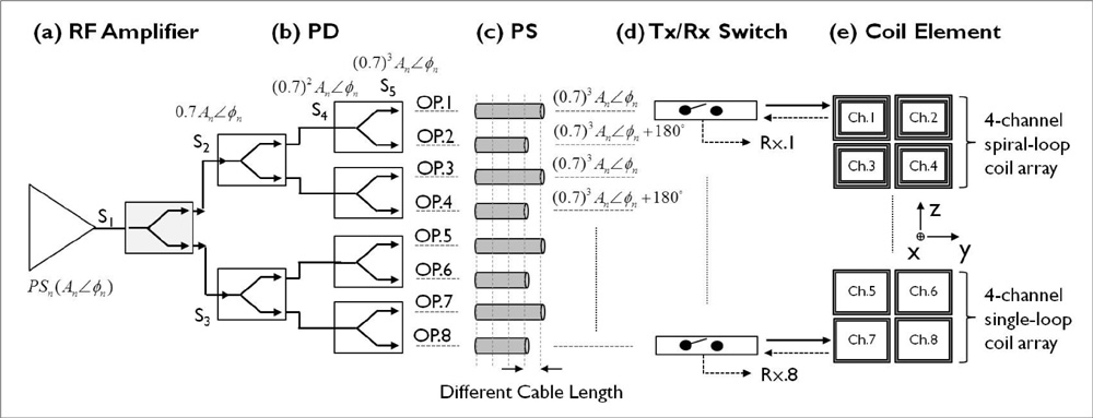
Fig. 3 RF signal pathway for two 4-channel TMJ coil arrays using the power divider (PD) and phase shifter (PS), and Tx/Rx switches. The RF signal comes from the (a) single-channel RF amplifier and is delivery to a (b) 2-way Wilkinson power dividers with -3dB power split and no phase shift. The final RF power signal is shifted via a (c) phase shifter using a coaxial cable delay. For the Tx/Rx operation, (d) Tx/Rx switches were inserted as a lumped element. The 8-output RF ports, two sets of coils with 4 each side, were connected to (e) each 4-channel TMJ coil arrays.

Fig. 4 Schematic circuit of the two-way Wilkinson power divider.
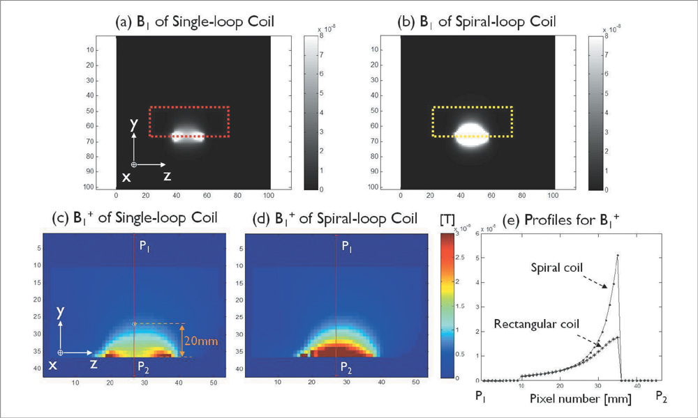
Fig. 5 Computer simulation of relative (a, b) B1 field distribution and (c, d) B1+ maps for single-channel single-loop and spiral-loop coil was acquired by FDTD calculation. The B1+ maps of each coil were compared after normalization with 3 µT in a location 20 mm apart from the coil plane. The color scale is expressed in terms of a fraction of the maximum scale value. (e) The B1+ profiles on the line of P1 and P2 (in Fig. 5c, d).
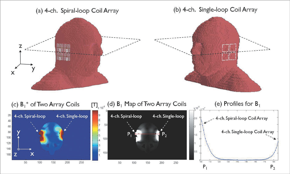
Fig. 6 Computer simulation results of (a) the 4-channel spiral-loop coil array and (b) 4-channel single-loop coil array, respectively in a human head model. (c) The B1+ maps and (d) B1 field in the central transverse plane (dotted line in (a, b)) at 300 MHz. (e) The B1 profile shown with blue line (P1-P2 line in (d)) indicates the corresponding SNR map.
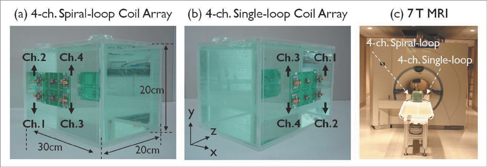
Fig. 7 Two types of 4-channel TMJ coil arrays; (a) the spiral-loop coil array and (b) the single-loop coil array. For the experimental setting, both coils are attached onto the distilled water phantom (composition: 1.25 gNiSO4 × 6H2O + 5 gNaCl per 1000 H2O, size 20 cm × 20 cm × 30 cm in the x, y, and z directions). (c) is the experimental setting at 7T MRI.

Fig. 8 Upper part; B1 field distributions in phantom obtained by GRE imaging for each 4-channel TMJ coil arrays for different FA values; 10°, 20°, 30°, 40°, and 60°. Lower part; B1+ maps obtained for different values of FA. FA was normalized for the central transverse plane at 7T.

Fig. 9 MRI images obtained from the TMJ region using 3D FLASH sequence (TR / TE / α= 16 / 3.42 ms / 10°, field-of-view = 200 × 200 mm, matrix size = 320 × 320, slice thickness = 0.6 mm, bandwidth = 200 Hz, and total acquisition time = 6 min 10 s). SNR maps in the TMJ image were obtained from both (a-i) 4-channel spiral-loop coil array (c-i) 4-channel single-loop coil array, respectively, while in the middle (b-i), a corresponding transverse slice are shown. In the bottom row (iii), SNR maps of the 4-channel spiral-loop coil array and the 4-channel single-loop coil array are shown. The numerical values shown are the SNR values. As shown 4-channel spiral-loop coil array has better image intensity profile than the single-loop coil for specific SNR value (dotted line of box indicate SNR of 30 and over).
Reference
-
1. Hoult DI, Richards RE. The signal to noise ratio of the nuclear magnetic resonance experiment. J Magn Reson. 1976. 24:71–85.2. Wiesinger F, Van de Moortele PF, Adriany G, Zanche ND, Ugurbil K, Pruessmann KP. Potential and feasibility of parallel MRI at high field. NMR Biomed. 2006. 19:368–378.3. Abduljalil AM, Robitaille P-ML. Macroscopic susceptibility in ultra high field MRI. J Comput Assist Tomogr. 1999. 23:832–841.4. Abduljalil AM, Kangarlu A, Yu Y, Robitaile P-ML. Macroscopic susceptibility in ultra high field MRI. II: acquisition of spin echo images from the human head. J Comput Assist Tomogr. 1999. 23:842–844.5. Bottomley PA, Andrew ER. RF magnetic field penetration, phase shift and power dissipation in biological tissue: implications for NMR imaging. Phys Med Biol. 1978. 23:630–643.6. Roschmann P. Radiofrequency penetration and absorption in the human-body: limitations to high-field whole-body nuclear magnetic resonance imaging. Med Phys. 1987. 14:922–931.7. Bomsdorf H, Helzel T, Kunz D, Roschmann P, Tschendel O, Wieland J. Spectroscopy and imaging with a 4 tesla whole-body mr system. NMR Biomed. 1988. 1:151–158.8. ZH Cho YB Kim KN Kim SM Hong . MRI system RF coil assembly with a birdcage transmit only coil and a pseudo-chain-link receive only coil array. US 7,733,088 B2. 2010.9. Wald LL, Wiggins GC, Potthast A, Wiggins CJ, Triantafyllou C. Design consideration and coil comparisons for 7T brain imaging. Appl Magn Reson. 2005. 29:19–37.10. Eberhard D, Bantleon HP, Steger W. Functional magnetic resonance imaging of temporomandibular joint disorders. Eur J Orthod. 2000. 22:489–497.11. Welker KN, Tsuruda JS, Hadley JR, Hayes CE. Radio-frequency coil selection for MR imaging of the brain and skull base. Radiology. 2001. 221:11–25.12. Zhang S, Gersdorff N, Frahm J. Real-time magnetic resonance imaging of temporomandibular joint dynamics. Open Med Imaging J. 2011. 5:1–7.13. Vaughan JT, Garwood M, Collins CM, et al. 7T vs. 4T: RF power, homogeneity, and signal-to-noise comparison in head images. Magn Reson Med. 2001. 46:24–30.14. Van de Moortele PF, Akgun C, Adriany G, et al. B1 destructive interference and spatial phase patterns at 7T with a head transceiver array coil. Magn Reson Med. 2005. 54:1503–1518.15. Alsop DC, Connick TJ, Mizsei G. A spiral volume coil for improved RF field homogeneity at high static magnetic field strength. Magn Reson Med. 1998. 40:49–54.16. Mueller MF, Blaimer M, Breuer F, et al. Double spiral array coil design for enhanced 3D parallel MRI at 1.5 Tesla. Concepts Magn Reson Part B Magn Reson Eng. 2009. 35:67–79.17. Staewen RS, Johnson AJ, Ross BD, Parrish T, Merkle H, Garwood M. 3D flash imaging using a single surface coil and a new adiabatic pulse, BIR-4. Invest Radiol. 1990. 25:559–567.18. Katscher U, Borner P, Leussler C, Van de Brink JS. Transmit SENSE. Magn Reson Med. 2003. 49:144–150.19. Adriany G, Van de Moortele PF, Ritter J, et al. A geometrically adjustable 16-channel transmit/receive transmission line array for improved RF efficiency and parallel imaging performance at 7Tesla. Magn Reson Med. 2008. 59:590–597.20. Kim KN, Darji N, Herrmann T, et al. Improved B1+ field using 16-channel transmit head array and an 8-channel pTx system at 7T. Proceedings of the 20th Annual Meeting of ISMRM. 2011. Montreal: 3220.21. Clare S, Alecci M, Jezzard P. Compensating for B1 inhomogeneity using active transmit power modulation. Magn Reson Imaging. 2001. 19:1349–1352.22. Mispelter J, Lupu M, Briguet A. NMR probeheads for biophysical and biomedical experiments: theoretical principles & practical guidelines. 2006. Imperial College London.23. Gabriel C. Internet document; URL: http://niremf.ifac.cnr.it/tissprop/#over.24. Eroglu S, Gimi B, Roman B, Friedman G, Magin RL. NMR spiral surface microcoils: design, fabrication, and imaging. Concepts Magn Reson Part B Magn Reson Eng. 2003. 17:1–10.25. Gimi B, Eroglu S, Leoni L, Desai TA, Magin RL, Roman BB. NMR spiral surface microcoils: applications. Concepts Magn Reson Part B Magn Reson Eng. 2003. 18:1–8.26. Constantinides C, Angeli S, Gkagkarellis S, Cofer G. Intercomparison of performance of RF coil geometries for high field mouse cardiac MRI. Concepts Magn Reson Part A. 2011. 38:236–252.27. De Zwart JA, Ledden PJ, Kellman P, van Gelderen P, Duyn JH. Design of a SENSE-optimized high-sensitivity MRI receive coil for brain imaging. Magn Reson Med. 2002. 47:1218–1227.28. Roemer PB, Edelstein WA, Hayes CE, Souza SP, Mueller OM. The NMR phased array. Magn Reson Med. 1990. 16:192–225.29. Wang J. A novel method to reduce the signal coupling of surface coils for MRI. Proceedings of the 4th Annual Meeting of ISMRM. 1996. –1434.30. Deppe MH, Parra-Robles J, Marshall H, Lanz T, Wild JM. A flexible 32-channel receive array combined with a homogeneous transmit coil for human lung imaging with hyperpolarized 3He at 1.5T. Magn Reson Med. 2011. 66:1788–1797.31. Morze CV, Tropp J, Banerjee S, et al. An eight-channel, nonoverlapping phased array coil with capacitive decoupling for parallel MRI at 3T. Concepts Magn Reson Part B Magn Reson Eng. 2007. 31:37–43.32. Kraff O, Bitz AK, Kruszona S, et al. An eight-channel phased array RF coil for spine MR imaging at 7T. Invest Radiol. 2009. 44:734–740.33. Yang QX, Wang J, Zhang X, et al. Analysis of wave behavior in lossy dielectric samples at high field. Magn Reson Med. 2002. 47:982–989.34. Collins CM, Yang QX, Wang JH, et al. Different excitation and reception distribution with a single-loop transmit-receive surface coil near a head-sized spherical phantom at 300 MHz. Magn Reson Med. 2002. 47:1026–1028.35. Dole CW. Coaxial cable insertion phase measurement and analysis. Accessed March 10, 2012. Internet document; URL: http://www.belden.com/pdfs/Techpprs/Wireless%20Market%20Web%20Phase%20Paper.pdf.36. Cunningham CH, Pauly JM, Nayak KS. Saturated double-angle method for rapid B1+ mapping. Magn Reson Med. 2006. 55:1326–1333.37. Collins CM, Smith MB. Calculation of B1 distribution, SNR, and SAR for a surface coil adjacent to an anatomically-accurate human body model. Magn Reson Med. 2001. 45:692–699.38. Collins CM, Smith MB. Signal-to-noise ratio absorbed power as functions of main magnetic field strength, and definition of "90°" RF pulse for the head in the birdcage coil. Magn Reson Med. 2001. 45:684–691.39. NEMA standards publication MS-2001.40. Dalkiz M, Pakdemirli E, Beydemir B. Evaluation of temporomandibular joint dysfunction by magnetic resonance imaging. Turk K Med Sci. 2001. 31:337–343.41. Maizlin ZV, Nutiu N, Dent PB, et al. Displacement of the temporomandibular joint disk: correlation between clinical findings and MRI characteristics. J Can Dent Assoc. 2010. 76:a3.
- Full Text Links
-
- Actions
-
Cited
- CITED
-
- Close
- Share
-
- Similar articles
-
- A Review on the RF Coil Designs and Trends for Ultra High Field Magnetic Resonance Imaging
- Dual Birdcage RF Coil for Leg MR Angiography
- Analysis of Endcap Effect for MRI Birdcage RF Coil by FDTD Method
- Reliability of MRI Using Endorectal Coil in Local Staging of Prostate Carcinoma
- A Projection-based Intensity Correction Method of Phased-Array Coil Images
