The path of placement of a removable partial denture: a microscope based approach to survey and design
- Affiliations
-
- 1Private Practice, Manalapan, NJ, USA. mamounjo@gmail.com
- KMID: 1974895
- DOI: http://doi.org/10.4047/jap.2015.7.1.76
Abstract
- This article reviews the topic of how to identify and develop a removable partial denture (RPD) path of placement, and provides a literature review of the concept of the RPD path of placement, also known as the path of insertion. An optimal RPD path of placement, guided by mutually parallel guide planes, ensures that the RPD flanges fit intimately over edentulous ridge structures and that the framework fits intimately with guide plane surfaces, which prevents food collecting empty spaces between the intaglio surface of the framework and intraoral surfaces, and ensures that RPD clasps engage adequate numbers of tooth undercuts to ensure RPD retention. The article covers topics such as the causes of obstructions to RPD intra-oral seating, the causes of food collecting empty spaces that may exist around an RPD, and how to identify if a guide plane is parallel with the projected RPD path of placement. The article presents a method of using a surgical operating microscope, or high magnification (6-8x or greater) binocular surgical loupes telescopes, combined with co-axial illumination, to identify a preliminary path of placement for an arch. This preliminary path of placement concept may help to guide a dentist or a dental laboratory technician when surveying a master cast of the arch to develop an RPD path of placement, or in verifying that intra-oral contouring has aligned teeth surfaces optimally with the RPD path of placement. In dentistry, a well-fitting RPD reduces long-term periodontal or structural damage to abutment teeth.
Keyword
MeSH Terms
Figure
-
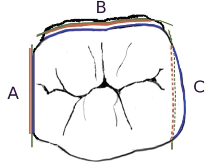
Fig. 1 Imaginary planes (green), that are parallel with the candidate RPD POP axes, appear 100% foreshortened when viewed using candidate viewing axes. The apical boundary (red) and the occlusal boundary (blue) of potential guide planes are shown relative to the imaginary plane. The boundaries appear essentially superimposed on the imaginary plane if the surface is parallel with the candidate RPD POP (A); the occlusal boundary appears axial to the apical boundary for a divergent surface (B); the apical boundary appears axial to the occlusal boundary for an undercut surface (C).
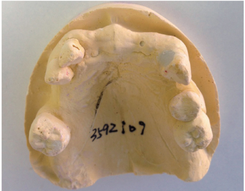
Fig. 2 The viewing angle of this cast, which (barely) shows the apical-facial line angle of the anterior edentulous ridge, is parallel to a candidate RPD POP that allows the anterior border of the RPD to seat into the apical-facial line angle of the anterior edentulous ridge. Unfortunately, the canines and molars appear severely undercut in this viewing perspective.
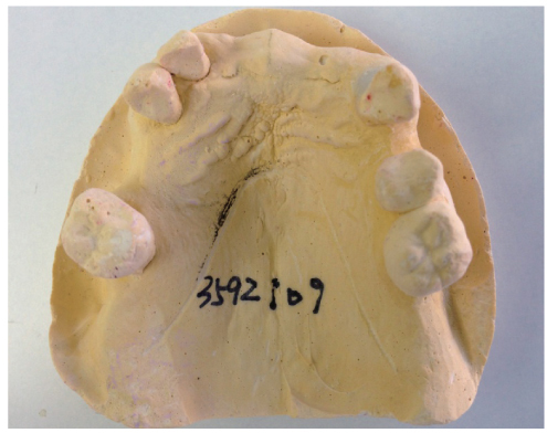
Fig. 3 The same cast as in figure 1, tilted such that the teeth surfaces facing the edentulous spaces appear more parallel with the axes of the viewing perspective. However, the anterior flange of an RPD that is made for the POP implied by this viewing perspective would not extend into the apical-facial line angle of the edentulous ridge, since the line angle is not visible in this perspective. A small circular void in the cast in the anterior ridge appears to shift approximately 2.5 mm. between the perspectives of the cast in figures 1 and 2, showing that the RPD would cover 2.5 mm. less facial-lingual width of the anterior ridge using the (more practical, but less esthetic) POP represented by this viewing perspective.
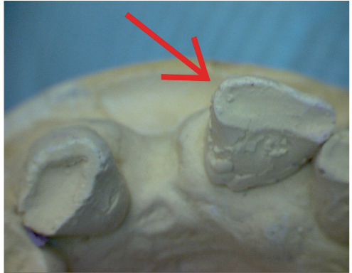
Fig. 4 A pre-operative diagnostic model is photographed using microscopes at the anterior aspect using a camera perspective or viewing axis that is parallel to the axes of a candidate RPD POP. This candidate RPD POP was selected because, in this viewing perspective, the apical-anterior line angle of the anterior edentulous ridge is almost visible. A red arrow indicates a line angle on the central incisor that is undercut relative to the candidate RPD POP.
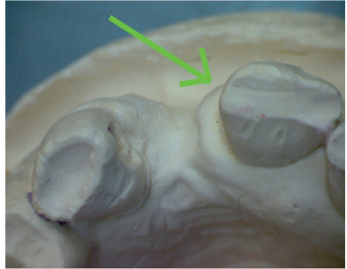
Fig. 5 A post-operative diagnostic model is viewed using microscopes at the anterior aspect using a camera perspective and visual axis that is approximately parallel to the axes of a same candidate RPD POP used to view the pre-operative model. A green arrow indicates the same line angle shown in the pre-operative model, after post-operative shaping of the line angle. The line angle surface now appears, in this visual perspective, to be more parallel with the axes of the candidate RPD POP that is represented by this visual perspective.
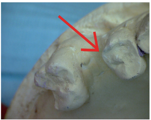
Fig. 6 A pre-operative diagnostic model is photographed using microscopes at the posterior aspect using a camera perspective or viewing axis that is parallel to the axes of the same candidate RPD POP that is used to view the anterior aspect in figures 4 and 5. A red arrow indicates a line angle on the premolar that is undercut relative to the candidate RPD POP.
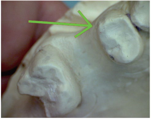
Fig. 7 A post-operative diagnostic model is viewed using microscopes at the right posterior aspect using a camera perspective and visual axis that is approximately parallel to the axes of a same candidate RPD POP used to view the pre-operative model. A green arrow indicates the same line angle shown in the pre-operative model, after post-operative shaping of the line angle. The line angle surface now appears, in this visual perspective, to be more parallel with the axes of the candidate RPD POP that is represented by this visual perspective. Note that the mesial surface of the molar is divergent relative to the RPD POP represented in this photo perspective.
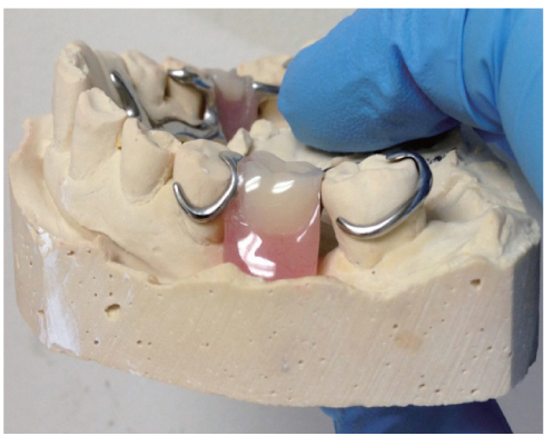
Fig. 8 A food-collecting space between the framework and the mesial surface of a molar that borders an edentulous space.
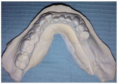
Fig. 9 An arch where, due to teeth inclinations and due to teeth crowns converging in an apical to occlusal direction, there was no path of placement with undercuts on strong teeth. The lower right premolars were structurally weak due to large restorations. The laboratory technician created a T-bar clasp with a thick metal arm, extending from the right posterior aspect of the framework, to clasp the right canine. The patient had this clasp removed due to esthetic concerns; the RPD would then shift during mastication, traumatizing the right posterior gingiva.
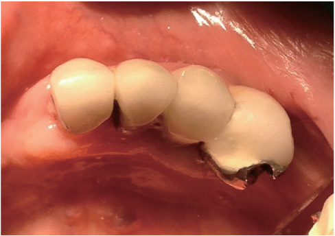
Fig. 10 The distal surface of the incisor (far left) is parallel with the viewing axis of this perspective, and may be acceptable as a guide plane, except that the canine keyway (far right) features a disto-lingual undercut in this viewing angle, and the keyway floor is not fully visible.
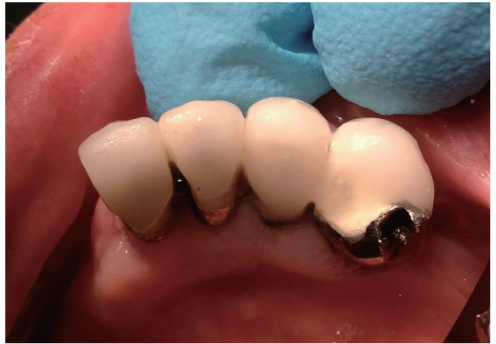
Fig. 11 In this viewing perspective, the keyway floor appears fully visible. However, the incisor disto-facial line angle (far left) appears heavily undercut. Contouring the incisor facial porcelain may destroy the crown, so the keyway must be re-shaped or removed.
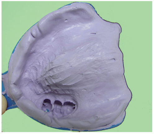
Fig. 12 This diagnostic impression shows a maxillary arch containing a three-unit fixed partial denture that contains two keyways, located at the extreme distal and extreme mesial aspects of the bridge, respectively. The viewing perspective of this photo is approximately parallel with the set of imaginary parallel axes that define the paths of placement created by the two keyways. Unusually, a segment of the facial aspect of the edentulous ridge, that is approximately 3 cm. in length, and is located mesial to the premolar, is undercut relative to the paths of placement of the bridge keyways. A dentist fabricated an RPD with a metal framework incorporating metal components that fit precisely into the two keyways. This RPD was initially obstructed during seating due to the RPD prematurely contacting the undercut 3 cm. edentulous ridge segment. The dentist made the RPD seat by extensively grinding away the intaglio surface of the aspect of the RPD that seated laterally to the undercut edentulous ridge segment. This resulted in a food-collecting empty space between the intaglio surface of the RPD and the undercut edentulous ridge segment. Later, the patient accidentally dropped the RPD from a short height, resulting in the fracture of the weakened, thinned out anterior acrylic resin segment in the vicinity of the undercut edentulous ridge segment. The RPD was eventually re-made successfully, after making a new framework, with a design such that the framework did not fit into the keyways. Fabricating the framework such that the framework bypassed the keyways permitted use of an RPD POP such that the entire facial aspect of the edentulous ridge was non-undercut relative to the RPD POP.
Reference
-
1. The glossary of prosthodontic terms. J Prosthet Dent. 2005; 94:10–92.2. Carreiro Ada F, Machado AL, Giampaolo ET, Santana IL, Vergani CE. Dual path: a concept to improve the esthetic replacement of missing anterior teeth with a removable partial denture. J Prosthodont. 2008; 17:586–590.3. Krol AJ, Finzen FC. Rotational path removable partial dentures: Part 1. Replacement of posterior teeth. Int J Prosthodont. 1988; 1:17–27.4. Krol AJ, Finzen FC. Rotational path removable partial dentures: Part 2. Replacement of anterior teeth. Int J Prosthodont. 1988; 1:135–142.5. Jacobson TE, Krol AJ. Rotational path removable partial denture design. J Prosthet Dent. 1982; 48:370–376.6. Suh JS, Billy EJ. Rotational path removable partial denture (RPD): conservative esthetic treatment option for the edentulous mandibular anterior region: a case report. J Esthet Restor Dent. 2008; 20:98–105.7. Baharav H, Ben-Ur Z, Laufer BZ, Cardash HS. Removable partial denture with a lateral rotational path of insertion. Quintessence Int. 1995; 26:531–533.8. Carr AB, Borwn DT, McCracken WL. McCracken's removable partial prosthodontics. 12th ed.St. Louis, Mo.: Elsevier Mosby;2011.9. Stratton RJ, Wiebelt FJ. An atlas of removable partial denture design. Chicago: Quintessence Pub. Co.;1988.10. Davenport JC, Basker RM, Heath JR, Ralph JP, Glantz PO. The removable partial denture equation. Br Dent J. 2000; 189:414–424.11. Davenport JC, Basker RM, Heath JR, Ralph JP, Glantz PO, Hammond P. Tooth preparation. Br Dent J. 2001; 190:288–294.12. Mamoun JS. A rationale for the use of high-powered magnification or microscopes in general dentistry. Gen Dent. 2009; 57:18–26.13. van As G. Magnification and the alternatives for microdentistry. Compend Contin Educ Dent. 2001; 22:1008–1012. 1014–1016.14. Napoletano D. Dental Operating Microscopes: Don't Equip an Operatory Without One. Inside Dent. 2007; 3(5):Available form: http://www.dentalaegis.com/id/2007/05/dental-operating-microscopes-do-not-equip-an-operatory-without-one.15. Owall B, Budtz-Jörgensen E, Davenport J, Mushimoto E, Palmqvist S, Renner R, Sofou A, Wöstmann B. Removable partial denture design: a need to focus on hygienic principles? Int J Prosthodont. 2002; 15:371–378.16. Rudd RW, Bange AA, Rudd KD, Montalvo R. Preparing teeth to receive a removable partial denture. J Prosthet Dent. 1999; 82:536–549.17. Bezzon OL, Mattos MG, Ribeiro RF. Surveying removable partial dentures: the importance of guiding planes and path of insertion for stability. J Prosthet Dent. 1997; 78:412–418.18. Zarb G, Watson RM, Hobkirk J. Guide planes. In : In : Bates JF, Neill DJ, Preiskel HW, editors. Restoration of the Partially Dentate Mouth. Proceedings of the International Prosthodontic Symposium of 1982; London: Quintessence;1984. p. 193–201.19. Waghorn S, Kuzmanovic DV. Technique for preparation of parallel guiding planes for removable partial dentures. J Prosthet Dent. 2004; 92:200–201.20. Mamoun J. Preparing fixed partial denture abutments such that they provide a path of placement free of undercuts. Gen Dent. 2012; 60:519–525.21. Bennani V, Shahmiri R. A simple method to transfer the selected path of insertion of a removable partial denture intraorally. J Prosthet Dent. 2009; 101:73–74.22. Burns DR, Unger JW. The construction of crowns for removable partial denture abutment teeth. Quintessence Int. 1994; 25:471–475.
- Full Text Links
-
- Actions
-
Cited
- CITED
-
- Close
- Share
-
- Similar articles
-
- A photoelastic study on the stress analysis under mandibular distal-extension removable partial denture with different design of the major connector
- Clinical application of mandibular removable partial denture using implant-supported surveyed crown: A case report
- A PHOTOELASTIC ANALYSIS ON TOOTH SUPPORTING STRUCTURE AND RESIDUAL RIDGE ACCORDING TO DENTURE DESIGN FOR REMAINING MANDIBULAR CANINES
- STRESS ANALYSIS AT SUPPORTING TISSUE OF ABUTMENT TEETH AND RESIDUAL RIDGE ACCORDING TO DENTURE DESIGN WITH REMAINING UNILATERAL POSTERIOR TEETH
- Implant-assisted removable partial denture using digital guide surgery in partially edentulous mandible: A case report
