Corrective Surgery Using Virtual Surgical Simulation and a Three-Dimensional Printed Osteotomy Guide: A Case Report
- Affiliations
-
- 1Department of Orthopedic Surgery, Korea University Ansan Hospital, Ansan, Korea
- KMID: 2545991
- DOI: http://doi.org/10.14193/jkfas.2023.27.3.112
Abstract
- A 74-year-old female patient, who underwent surgery for a left distal tibiofibular fracture 40 years earlier, visited the hospital with an ankle varus deformity due to malunion. The patient complained of discomfort while walking due to the ankle and hindfoot varus deformity but did not complain of ankle pain. Therefore, correction using supramalleolar osteotomy was planned, and through virtual surgical simulation, it was predicted that a correction angle of 24° and an osteotomy gap open of 12 mm would be necessary. An osteotomy guide and an osteotomy gap block were made using three-dimensional (3D) printing to perform the osteotomy and correct the deformity according to the predicted goal. One year after surgery, it was observed that the ankle varus was corrected according to the surgical simulation, and the patient was able to walk comfortably. Thus, for correction of deformity, virtual surgical simulation and a 3D-printed osteotomy guide can be used to predict the target value for correction. This is useful for increasing the accuracy of correction of the deformity.
Figure
-
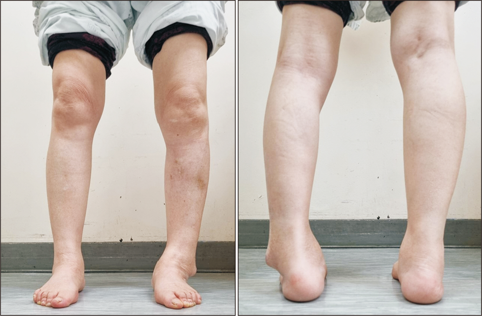
Figure 1 Initial clinical photographs.
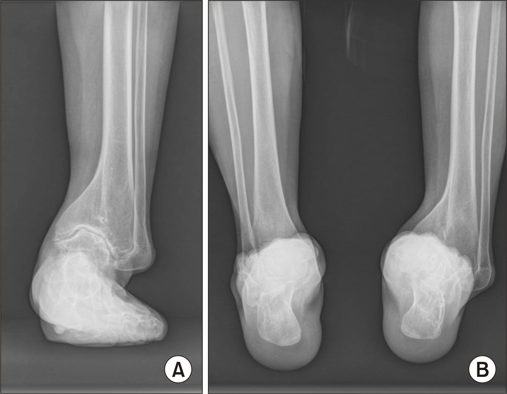
Figure 2 Preoperative standing anteroposterior radiograph of the ankle (A) and hindfoot alignment view (B).
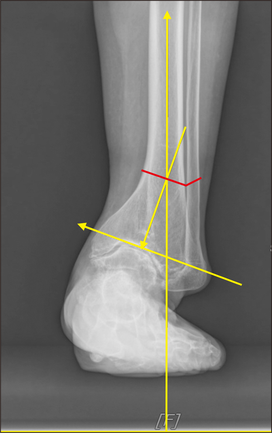
Figure 3 The red line indicates the osteotomy plane, which passes through the center of rotation axis.
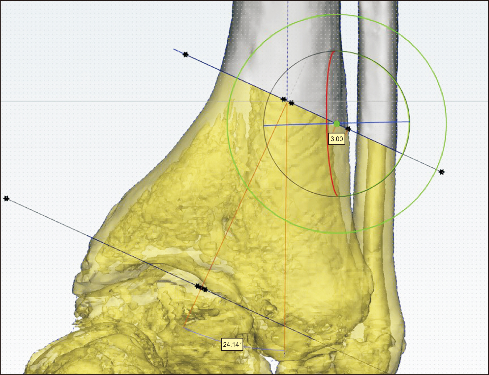
Figure 4 The light green dot, which is the center of rotation, is located 3 mm medially from the lateral cortex.
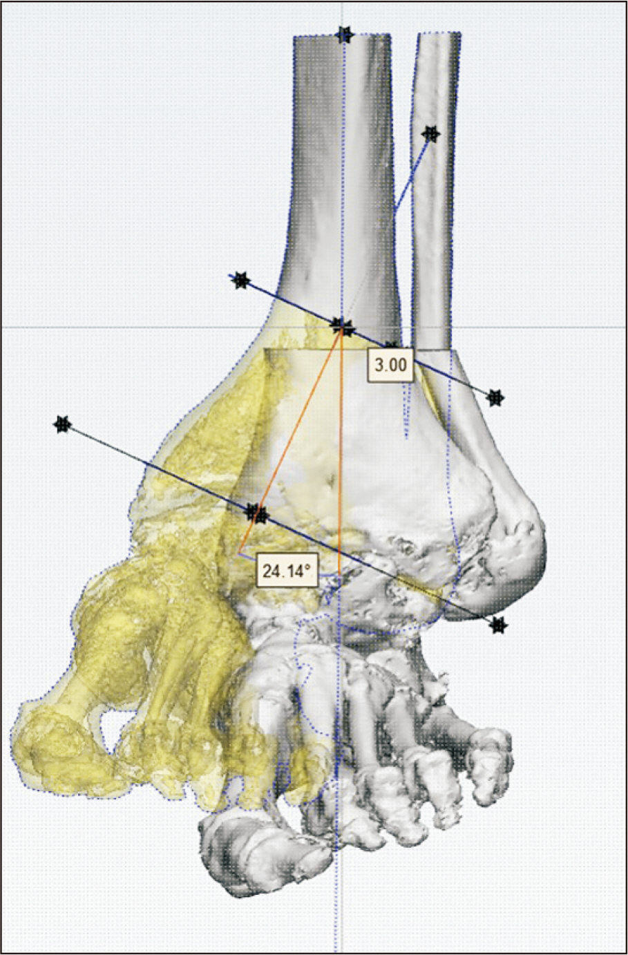
Figure 5 A correction angle of 24° was predicted to align the proximal and distal tibial axes after correction.
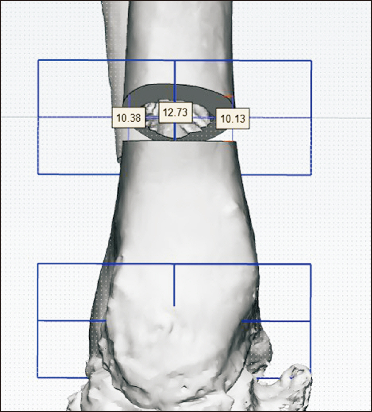
Figure 6 Prediction of opening height (mm) of tibial osteotomy site for correction.
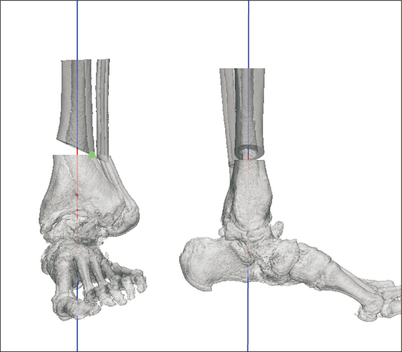
Figure 7 After correction, the distal and proximal axes of the tibia align with each other on the 3-dimensional image.
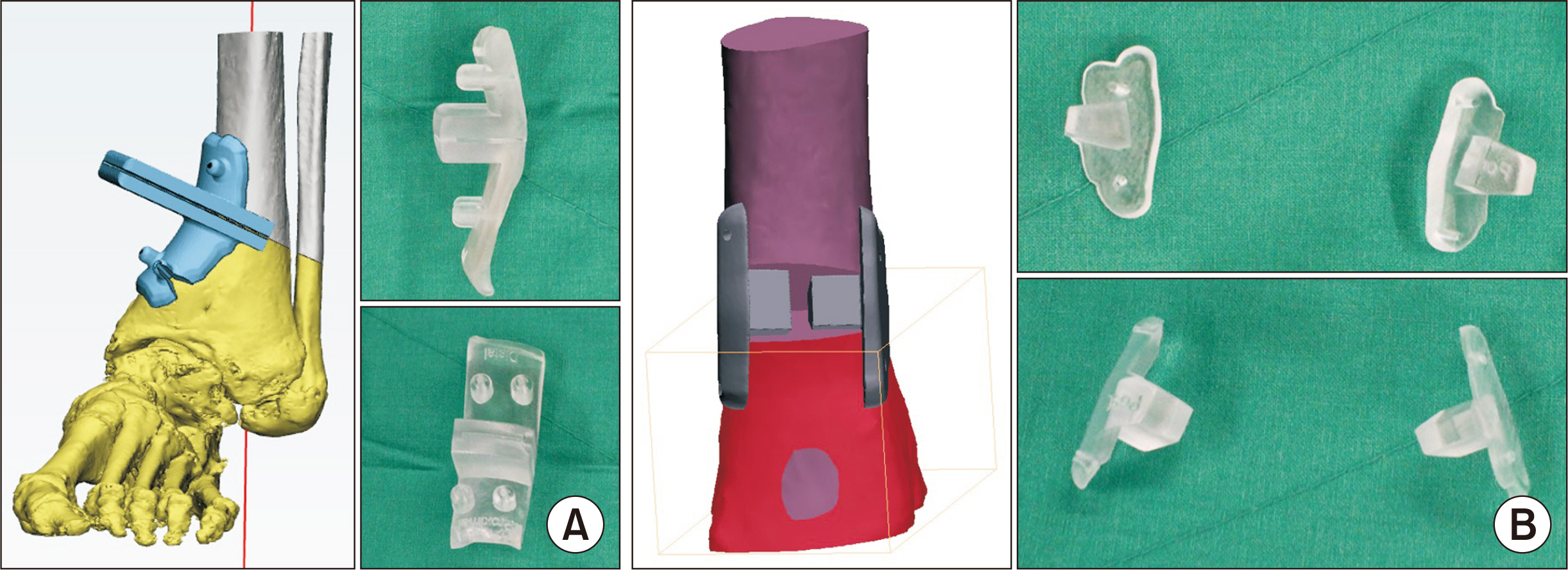
Figure 8 Three-dimensional printed osteotomy guide (A) and blocks (B).
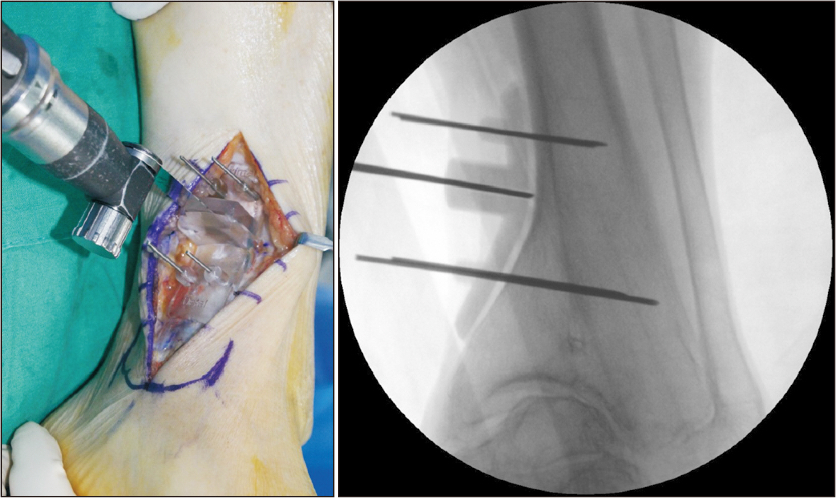
Figure 9 Sawing along the osteotomy guide.
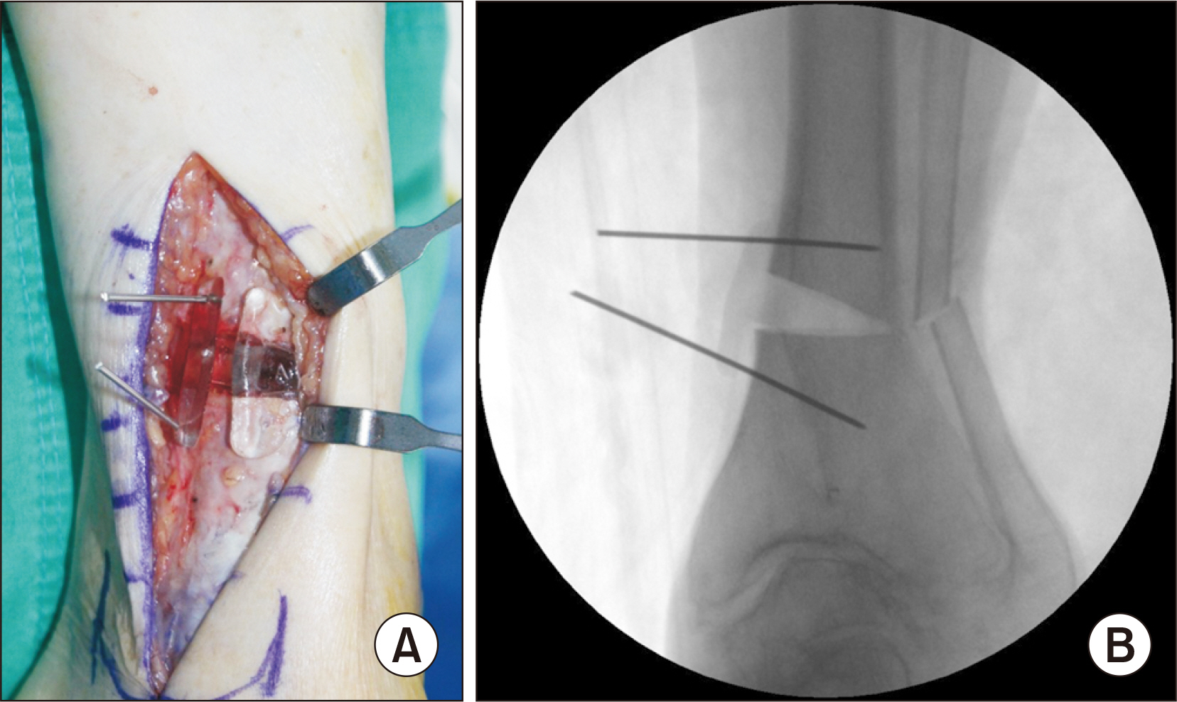
Figure 10 After inserting the 3-dimensional printed osteotomy blocks in the anterior and posterior regions (A), it was confirmed that the target degree of correction was achieved on the C-arm (B).
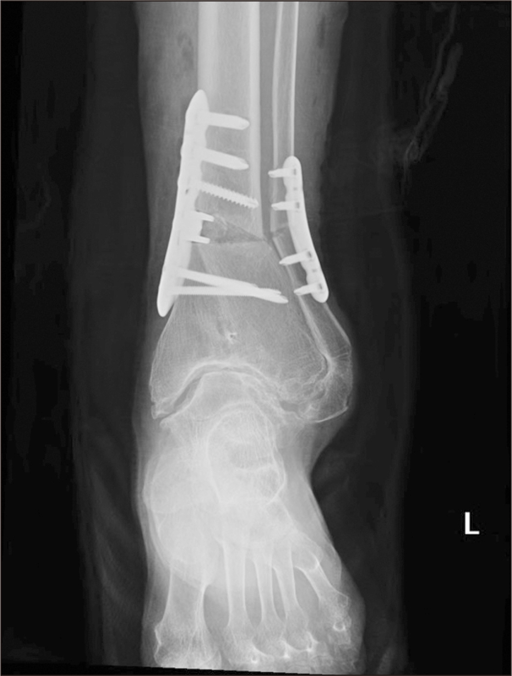
Figure 11 An anteroposterior radiograph of the ankle taken immediately after surgery.
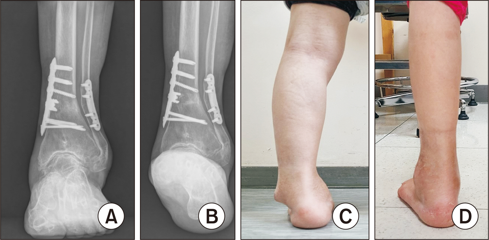
Figure 12 Standing anteroposterior radiograph of the ankle (A), and hindfoot alignment view (B) taken 1 year after surgery. Clinical photographs of the hindfoot before (C) and after surgery at 1 year (D).
Reference
-
1. Bastawrous S, Wu L, Strzelecki B, Levin DB, Li JS, Coburn J, et al. 2021; Establishing quality and safety in hospital-based 3D printing programs: patient-first approach. Radiographics. 41:1208–29. doi: 10.1148/rg.2021200175. DOI: 10.1148/rg.2021200175. PMID: 34197247.
Article2. Pabst A, Goetze E, Thiem DGE, Bartella AK, Seifert L, Beiglboeck FM, et al. 2022; 3D printing in oral and maxillofacial surgery: a nationwide survey among university and non-university hospitals and private practices in Germany. Clin Oral Investig. 26:911–9. doi: 10.1007/s00784-021-04073-6. DOI: 10.1007/s00784-021-04073-6. PMID: 34278522.
Article3. Pugliese L, Marconi S, Negrello E, Mauri V, Peri A, Gallo V, et al. 2018; The clinical use of 3D printing in surgery. Updates Surg. 70:381–8. doi: 10.1007/s13304-018-0586-5. DOI: 10.1007/s13304-018-0586-5. PMID: 30167991.
Article
- Full Text Links
-
- Actions
-
Cited
- CITED
-
- Close
- Share
-
- Similar articles
-
- Genioplasty using a simple CAD/CAM (computer-aided design and computer-aided manufacturing) surgical guide
- Unilateral intraoral vertical ramus osteotomy based on preoperative three-dimensional simulation surgery in a patient with facial asymmetry
- Computer Simulation Surgery for Mandibular Reconstruction Using a Fibular Osteotomy Guide
- Surgery-first approach using a three-dimensional virtual setup and surgical simulation for skeletal Class III correction
- Surgical Stent Fabrication and Clinical Application for Orthognathic Surgery Using Cone-Beam CT
